


– 10 –
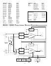
The final output stage utilizes lateral MOSFETs; four pairs are used for each channel in the 9505 and three pairs in the
9303. These devices, unlike conventional bipolar transistors do not exhibit “thermal runaway.” Thermal runaway is a
phenomenon whereby a transistor heats up as it draws more current, which causes it to get hotter, and conduct more
current, and so on until the device self destructs. Since the MOSFETs are inherently self protecting, no sonically
degrading, complex circuitry is required to monitor and protect the devices. The lateral MOSFETs also have a linear input
to output transfer function. Their connection in circuits and their operating characteristics are very similar to vacuum
tubes, which is perhaps responsible for their widely recognized sonic trait of being “musical” and non-fatiguing.
Operation of the transconductance stage is a major factor in the reproduction quality of the amplifier. The number of
MOSFETs used at the output stage of the 9303 and 9505 imposes sufficient capacitive load on the transconductance
stage that if a conventional Class A stage were used (having intrinsically a 2:1 limit on peak-to-quiescent current) it would
begin to show “stress” at the higher audio frequencies. The newly perfected DIABLO driver system (Dynamically
Invariant A-B Linear Operation; patent application in progress) satisfies the current headroom requirement by smoothly
and continuously varying the current transfer ratios of the two transconductance paths, under the control of the signal
current itself. This implementation allows the current transfer ratio of one path to be smoothly and continuously reduced
to zero while the other is smoothly and continuously increased by a factor of two. What is remarkably new here is that
when this normally-limiting 2:1 value is reached there is now about 14dB of additional, perfectly linear current
headroom left to drive the MOSFETs! The result is a dramatic decrease in high-frequency distortion combined with
higher ultrasonic stability – the “Holy Grail” of amplifier design.
The power supply utilizes a UI style transformer with a separate primary for each channel. The transformer has a separate
secondary for each channel high voltage power supply, each feeding a conventional split full wave bridge rectifier. High
voltage power supply capacitance is 20,000µF per rail for each channel for the 9505 and 5,000 for the 9303. The third
transformer secondary feeds a regulated supply for the input stage and driver circuitry. Low voltage power supply
capacitance is 1,000µF per rail, with additional decoupling for each channel.
CALIBRATION
Common Mode Rejection:
The input common mode null is adjusted by the trim pot R1 (R101 for the left channel). The CMRR should be greater
than 75dB below rated output. If the CMRR requires adjustment, feed the amplifier input with a common mode signal
and adjust R1. Disconnect the power to the amplifier before removing the cover. Use a sinewave generator set to 1
volt output at 1kHz. Connect the generator signal output to the tip and ring of a 1/4" plug and ground to the sleeve. Plug
this into the amplifier input. Connect an AC voltmeter to the amplifier output binding posts. Adjust R1 to give the lowest
voltage output from the amplifier. For a temporary adjustment when a signal generator and voltmeter are not available,
use an FM tuner and tune it to an unused station as your signal source, and connect the output to the amplifier as
described above. Connect the amplifier output to a small full range speaker and adjust R1 for the lowest output from
the speaker.
Bias:
The bias control establishes the quiescent Class AB output current of the amplifier. The bias should not need
readjustment from the factory setting; however, if the amplifier is repaired and output devices have been changed, or
if the two channels of the amplifier do not run at the same temperature, calibrating the bias is necessary. Disconnect
the power to the amplifier before removing the cover. To adjust the bias, disconnect the input and speakers and remove
the B+ fuse for that channel. Connect an amp meter across the now vacant fuse clips and adjust R45 (R145 for the left
channel) to get a current reading of 300mA for the 9303, 400mA for the 9505.