


GENERAL
TROUBLESHOOTING
HINTS
GROUND
LOOPS
4)
5)
6)
7)
8)
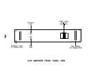
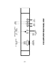
Apply power to the amplifier, and allow the unit to thermally stabilize for about three minutes. (If
using an analog meter, and the meter reads backwards, temporarily remove power and reverse
the meter leads.)
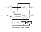
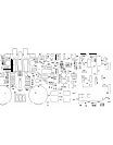
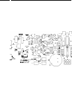
Again referring to the diagram, locate the trimmer potentiometer labelled Pl for the left channel,
or Pl 01 for the right channel. (NOTE: Do not confuse these trimmers with those labelled P2 and
P102:
these are for distortion control and require specialized test equipment to adjust.) Using a
small screwdriver, adjust the trimmer for a measured current of 130
mA.
Remove power from the amplifier. Wait about one minute for the power supply to discharge, and
remove the meter connections. Replace the fuse.
Repeat steps #2, 3, 4, 5 and 6 for the other channel.
Replace the cover.
The 9130 Amplifier contains five internal fuses: one for AC line power, and four for DC power supplies.
These fuses should not generally blow unless a malfunction has occurred. These fuses should be
replaced only by a qualified technician, and only with the exact type(s) and rating of fuse(s) originally
supplied. If a fuse is replaced and blows again within a short time, check all output connections for short
circuits, or abnormally low speaker load impedances. If all connections and load conditions appear
to be correct, disconnect all power immediately and return for service.
If all controls, fuses, cables, etc. seem to be functioning properly, a process of one-at-a-time
component substitution should be employed until the defective unit is identified. If only one channel
is not functioning properly, a one-at-a-time reversal of interconnect and speaker cables from left to right
should reveal the malfunctioning component.
Ground loops are characterized by a low level hum or buzz in the system. Loops are caused by a
voltage potential difference between two points in a ground circuit, and aggravated when multiple paths
for a given circuit exist. Noise-free audio performance is dependent upon all grounds being at the same
potential, with a single path for each ground connection. Ground loops can exist in two forms: 1) loops
created in audio interconnects, and 2) loops created between earth grounded chassis.
Mounting components to a rack with metallic rails may introduce ground loops between associated
equipment, because the rails can introduce a second ground path. The extent of this problem will
depend on the grounding arrangements of associated equipment. Ground loops can occur in non-
rackmounted equipment, though it is less common.
If ground loops occur, and any other component in the system has a three wire grounded power cord,
the first step should be to use a ground adaptor (with the ground tab or wire of the adaptor not
connected) on the power cord plug of the preamplifier. DO NOT cut off the grounding pin on the plug!
It may be necessary to use additional adaptors on other grounded components if more than two
components are earth grounded. (In other words, only one earth ground per system should exist.)
Another potential source of multiple earth grounds is from coaxial antenna or cable service feeds for
FM or video sources, which usually are (and should be) earth grounded. The ground adaptor(s) should
cure this grounding problem as well.
WARNING: The use of ground adaptors (with the ground tab or wire of the adaptor discon-
nected) will eliminate the safety feature of the grounded power cord. This safety feature is
intended to reduce the risk of electric shock should an internal fault in the equipment result in
an electrically “live” chassis. Therefore, this method of ground isolation should be employed
only when absolutely necessary, rather than as a general practice. When using a ground
adaptor for isolation, make sure that the power cord plug is inserted into the receptacle in the
same orientation as if no adaptor were present, to maintain the same hot/neutral polarity.
-ll-