CHANGING LINE
VOLTAGE RATING
ADJUSTING BIAS
The 9130 Amplifier is equipped with a simple means to adjust the AC line voltage rating for 100, 120
or 230 volts AC,
50/60
Hz. The configuration is
labelled
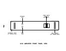
above the power cord connector. If the amplifier
will be used in a location that requires a different line voltage, use the following procedure to change
the configuration. Review the modification instructions before attempting this procedure. If any doubts
exist about one’s ability to change the line voltage, it is advisable that the procedure be conducted by
a qualified technician.
NOTE: Units wired for 230 VAC may be used over a range of 220 to 240 VAC. No compromise in
safety or performance will result from operation within this range.
WARNING! UNPLUG THE UNIT FROM AC POWER BEFORE ATTEMPTING THIS PROCEDURE.
FAILURE TO DO SO CAN RESULT IN SEVERE ELECTRICAL SHOCK.
1)
2)
3)
4)
5)
Remove the top cover by removing the four hex head screws (two on each side).
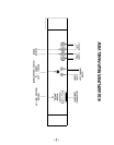
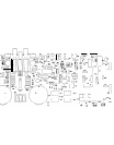
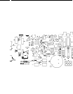
Using the diagram “Component Layout” as a guide, find the white Voltage Selector plug on the
printed circuit board located behind the front panel Power Switch. Note that this plug has several
alternate positions. Each position is
labelled
for where the end of the plug is to be aligned for each
appropriate voltage. Move this plug to the new desired position, making sure that the plug is fully
seated on the mating pins.
Depending upon which new voltage is chosen, it may be necessary to change the AC line fuse.
Locate the clip-mounted Line Fuse adjacent to the Voltage Selector plug. Replace the fuse with
a new slow-blow fuse as follows:
100 and 120 VAC: 5 amp
230 VAC: 2.5 amp
NOTE: For units wired at 100-120 VAC, the AC line fuse should be a 1/4 x 1-1/4” size, and
approved by UL/CSA For units wired at 230 VAC, the fuse should be a 5 x 20mm size, and
approved according to IEC 127.
Replace the cover.
Obtain a new voltage configuration label from the factory, and affix over the original markings on
the rear panel. Alternately, prepare a small self-adhesive label and indicate the new voltage with
permanent ink. Relabelling the unit is a vital safety requirement, particularly if the amplifier is sold
to a new owner.
The 9130 Amplifier employs a single control per channel to set the bias operating point of the output
stage. This bias point is factory set, and normally should not require adjustment for the life of the
product. However, should improper bias be suspected, or if repairs have been made that would require
a readjustment of bias, the following procedure should be used. Review the instructions before
attempting this procedure.
If any doubts exist about one’s ability to set the bias, it is advisable that the
procedure be conducted by a qualified technician.
WARNING! UNPLUG THE UNIT FROM AC POWER BEFORE ATTEMPTING THIS PROCEDURE.
FAILURE TO DO SO CAN RESULT IN SEVERE ELECTRICAL SHOCK.
REQUIRED TEST EQUIPMENT: Milliammeter capable of measuring at least 130
mA.
1)
Remove the top cover by removing the four hex head screws (two on each side).
2)
Using the diagram “Component Layout” as a guide, find the fuses labelled Fl and F2 for the left
channel, or Fl 01 and
F102
for the right channel.
3)
Working on one channel at a time, remove either one (and only one) of the fuses.
Connect the
milliammeter to the two fuse clips, and set the meter to a scale capable of measuring at least 130
mA.
WARNING! THE NEXT STEP OF THIS PROCEDURE CAN EXPOSE THE OPERATOR TO
UNINSULATED HIGH VOLTAGES. KEEP ALL BODY PARTS CLEAR OF THE INTERNAL
CIRCUITRY OF THE AMPLIFIER.
-lO-