HEADPHONE
AMPLIFIER
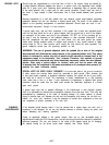
Internal signal grounding has been carefully routed to follow the signal path from the input jacks,
through the Selector System, through the Volume and Balance Controls, and finally to the line
amplifier. All power supply ground paths are returned to a single “star” ground point at the power
supply to minimize ground modulations. Extensive use of ground planes and interchannel shields
maximize inter-channel separation.
For units wired for 100-120 VAC, the power supply is kept “on” at all times so that all circuitry is
maintained at optimum operating temperature, for maximum fidelity as soon as the system is used.
The front panel Power Switch operates the Switched Outlets only, to turn on associated system
components.
For units wired for 200-240 VAC, the Power Switch controls the preamplifier’s power supply. This
switch may be left “on” at all times, if desired, to maintain optimum operating temperature.
The Headphone Amplifier utilizes a separate high-slew rate operational amplifier to drive the high
current demands of headphone operation. This relieves the Line Amplifier from the additional burden
of driving difficult headphone loads, and leaves the main signal path uncompromised for signals to
power amplifiers.
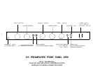
The Output Off Switch turns off both line outputs, to be used when listening to headphones only, or
as a system muting switch.
ADDITIONAL INFORMATION
INSTALLING
PHONO OPTION
If the 915 Preamplifier was purchased without the Phono Option, the Phono/Aux 1 input is a line level
input, and cannot be used with a turntable. To convert this input for use with a turntable, purchase
the 915 Phono Option Accessory from your Hafler Dealer. Review the installation instructions before
attempting this procedure. If any doubts exist about one’s ability to install the Phono Option, it is
advisable that the procedure be conducted by a qualified technician.
WARNING! UNPLUG THE UNIT FROM AC POWER BEFORE ATTEMPTING THIS PROCEDURE.
FAILURE TO DO SO CAN RESULT IN SEVERE ELECTRICAL SHOCK AS WELL AS DAMAGE TO
THE PREAMPLIFIER AND/OR PHONO BOARD.
1)
2)
3)
4)
Place the preamplifier on a soft, protective surface.
Remove the eight allen head screws (four
on each side), and six phillips head screws (three each on top and bottom), securing the top and
bottom covers. Remove covers. Carefully remove the plastic plug covering the MC/MM switch
hole by squeezing the prongs inside the chassis and prying out the plug.
Find the three wire jumpers on the main printed circuit board, located near the Phono/Aux input
jacks, labelled RJ5, RJ7, and RJ8. Remove the three jumper wires as shown. These jumpers
may be de-soldered or clipped out.
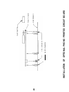
Refer to the diagram “Installation Of Optional Phono Printed Circuit Board”. Push the MC/MM
switch to the “in” position to ease installation of the phono board. Carefully guide the phono board
onto the main board, checking to make sure that all the electrical connector pins are aligned with
their mating parts before completely seating the phono board onto the three plastic standoffs.
It should snap into place with no free play. Double check that all four pins of each of three
connectors have been inserted completely.
If some of the pins have not properly seated, squeeze the prongs of the three plastic stand-
offs to release the phono board. Straighten any bent pins before re-attempting installation.
Add the button to the shaft of the MC/MM switch. Unless modifying the cartridge loads at this
time, replace the covers. (See Installing Cartridge Loads).
-12-


