


the binding posts. If you have lost the cable
binding post tool then a large screwdriver will
also work, but be careful not to overtighten
the binding posts as they may be damaged.
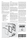
The RAM1 has two parallel 10 kOhm input
connectors: a balanced XLR and an unbal-
anced RCA. For longer cable connection
lengths (>10m or >30ft) a balanced line
connection is recommended as it offers
better immunity to external interference.
However, the RCA connection method
is more commonly available and usually
works as well for shorter connection lengths
in less electrically noisy environments. Do
not use both inputs at the same time. Con-
sult your Genelec dealer for the choice of
signal cables.
The RAM1 has a provision for remote control-
led switching between “ON” and “STANDBY”
modes. The “REMOTE CONTROL” connec-
tor block has two connector pairs: 1-2 for a
12 V DC trigger remote control and 3-4 for
an external switch or relay type (contact
closure) remote control (see Table 2). Do not
connect two remote controls to the amplifier
at the same time.
Space requirement for the RAM1
amplifier
The dual 120 W power amplifiers of a RAM1
unit generate a large amount of heat when
used at full power. To avoid overheating,
ensure that there is good airflow around the
amplifier and no external heat sources close
to it. We recommend installing the RAM1
into a well ventilated equipment rack using
its dedicated RM1 rack mount kit.
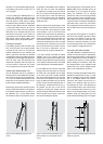
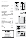
If the RAM1 amplifier is placed in a cabinet,
on a shelf or into an equipment rack without
its dedicated RM1 rack mount kit, there must
be at least 100 mm (4”) of free space behind,
150 mm (6”) above and 50 mm (2”) on both
sides of the amplifier to ensure adequate
cooling (see figure 8).
Mounting the RAM1 amplifier to an
equipment rack
We recommend that you use the Genelec
RM1 rack mount kit when installing the
RAM1 amplifier in an equipment rack. Make
sure that the space above and below the
RAM1 is uncluttered and there is a space
of 100 mm (4”) or more behind the ampli-
fier. The space behind the amplifier must be
well ventilated. If the temperature inside the
rack is likely to rise close to RAM1’s maxi-
mum ambient temperature of 35° C (95° F),
we recommend installing ventilation fans to
ensure that the thermal protection is not acti-
vated prematurely.
Attach the RAM1 to the RM1 rack mount with
two M3 screws provided with the rack mount
kit. The screws go through the holes on the
RM1’s shelf plate (see Figure 9 ). Each RM1
can take three RAM1 units. Two blanking
plates are provided to cover empty spaces
in the rack if only one or two RAM1’s are
installed.
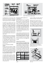
Setting the input sensitivity
The input sensitivity of each speaker can be
made to match that of the decoder or other
source by use of the input sensitivity control
on the amplifier’s front panel (see figure 6).
A small screwdriver is needed for the adjust-
ment. The manufacturer default setting for
this control is -6 dBu (0.389V, fully clockwise)
which gives SPL of 100 dB @1m with -6 dBu
input level. Note that to get the full output
level of 110 dB SPL, an input level of +4 dBu
Figure 6. Front panel of the RAM1 amplifier
Figure 7. Rear panel of the RAM1 amplifier
(1.22V) is needed in this setting. Most pre-
amplifiers are capable of this output level.
Setting the room response controls
The acoustic response of the system may
have to be adjusted to match the acoustic
environment and personal taste. See Table
3 for suggested room response control set-
tings in differing acoustic environments. If
the sound is found subjectively too bright, set
Figure 8. Minimum space requirement of
the RAM1 amplifier when not installed with
Genelec RM1 rack mount.
Figure 9. Attaching the RAM1 to Genelec RM1
rack mount
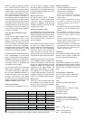
Table 2. Remote control connectors on the
RAM1.
Remote
control type
Pole or
contact
Connect to
remote control
input pin no.
+ 112 V DC
remote
control
- 2
Contact 1 3External
switch or
relay
Contact 2 4
Connect only one remote control unit at a time