


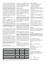

See Table 1 for recommended cable gauges.
The binding posts accept a cable up to 6
mm
2
(9 gauge).
If you are installing the AIW26 system to an
existing wall, examine the walls thoroughly
for the shortest and least obstructed cable
route. Be careful to avoid cutting or drilling
into electrical wires, ventilation or water pipes.
These are often visible in the attic, basement
or crawl space below the floor. All of this is
of course much easier when the installation
takes place in an unfinished wall where the
wall structure is still open. In both cases it is
a good idea to route the speaker cables away
from electric, video or phone cables, which
might induce hum into the speaker system.
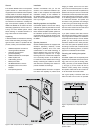
Painting the speakers
The speaker grill frame and the metal mesh
part of the grill insert can be spray painted
to match the wall colour. Do not paint the
speaker cabinet itself, or try to paint the grill
frame or grill insert while they are attached
to the speaker. Remove the metal mesh from
the grill insert to avoid clogging the grill insert
cloth with paint. Paint the grill frame and
metal mesh separately with a thin spray. Do
not use brushes or rollers. Be very careful
not to clog the holes on the mesh with paint.
Installing the AIW26 speaker unit
Use the cardboard wall cut-out template to
find the location for the AIW26. The template
also shows the position of the speaker driv-
ers, so you can easily find the placement that
brings them to the optimum position as out-
lined in chapter “Speaker placement”.
Examine the wall structure carefully to find a
clearly unobstructed location for the speaker.
The speaker cabinet requires a minimum of
88 millimeters (3
1
/
2
”) of free depth behind
the sheetrock. Keep in mind that the mount-
ing brackets of the AIW26 need a clearance
inside the wall of at least 125 millimeters
(5”) above the top edge of the hole and 65
mm (2
9
/
16
”) below the lower edge. Also note
that the grill frame is wider and taller than
the hole and requires about 30 millimeters
(1
3
/
16
”) of smooth wall surface around all
sides of the hole.
When you have found a good location, check
that the template is level and trace the hole
onto the wall with a pencil along the outline
of the template. If you are not sure that the
chosen part of wall is free from obstructions,
you can start by making a smaller hole at the
center of the marked area through which you
can probe the inside of the wall. Use a dry-
wall saw and make the first cut at a 45° angle
toward the center of the hole so you can put
the cut piece back in if the location is unsuit-
able. If you find no obstructions, you can
make the final cut along the marked lines.
If you have already connected the RAM1
amplifier units to the system, select the
speaker that has the same ID number as the
amplifier it will be driven by. Check the polarity
of the speaker cables and attach the cables
to the binding posts of the AIW26 speaker.
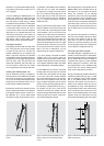
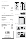
Lift the AIW26 into the hole top end (cable
binding posts) first (see Figure 3) and push
the lower end of the speaker onto the edge
of the hole. Push both mounting brackets
fully up and hold them there as you push the
lower half of the speaker into the wall (see
Figure 4). When the speaker is in the correct
position, pull the mounting brackets down. If
the wall cavity is deeper than 95 mm (3
3
/
4
”),
the speaker can drop into it. This can be
avoided by mounting the speaker with the
grill frame loosely attached. Screw the frame
screws only half way in to allow some move-
ment while installing the speaker.
Attach the grill frame to the speaker with six
M6x60 Phillips screws provided with the kit
(see Figure 5). As you tighten the screws
evenly, the sheetrock will be clamped
between the ends of the mounting brackets
and the grill frame and the speaker will be
firmly attached to the wall. NOTE! Overtight-
ening the screws will bend and damage the
grill frame. Keep a close look on the frame
as you tighten the screws and stop when you
see the metal base of the frame starting to
bend.
The grill insert has magnets on one side to
hold it onto the speaker’s grill frame. Attach
the insert on the speaker so that its cross-
piece does not cover the drivers. Be very
careful not to dent the grill frame if you have
to remove the grill insert. Use a wide piece of
wood or plastic to wedge the insert out.
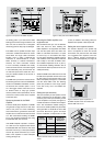
Connecting the RAM1 amplifier
The RAM1 amplifier is designed to be con-
nected to a line level output of a preamplifier,
Surround Sound processor or other low level
source. NOTE! Never connect the RAM1 to
a speaker level output of a power amplifier!
Before making the connections, check that
the voltage selector on the amplifier’s back
panel is set to the correct voltage and the
power on all components is turned off.
Start by connecting the speaker cables to the
amplifier’s binding posts (see Fig. 7). Check
that the amplifier’s serial number matches
that of the AIW26 speaker unit which it
will power. The number can be found on a
sticker on the speaker’s reflex port and on
the amplifier’s top cover. If the speakers are
not yet installed, make a note of which
ampli-
fier is connected to each channel so you can
find the correct AIW26 speaker unit for every
amplifier. Check the cable polarity and use
the provided cable binding post tool to tighten
Figure 3. Lift the AIW26’s top end into the
cut-out
Figure 4. Lift the mounting brackets up and
push the lower end of the speaker into the
cut-out
Figure 5. Pull the mounting brackets down and
attach the grill frame