


Page 5
15
16
17
18
19
20
21
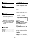
SCALE READING
CARTRIDGE HEIGHT
(mm)
0
1
2
3
4
5
6
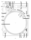
L (WHITE)
R (RED)
GND (Spade Lug)
MIXER OR
RECEIVER
OUTPUT CONNECTORS
PHONO L CHANNEL
PHONO R CHANNEL
GND Screw
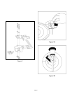
4. Place TONE ARM (5) on ARM REST (9) and lock it in place
with the ARM CLAMP (8).
5. With the TONE ARM (5) locked on the ARM REST (9), hold the
COUNTERWEIGHT (7) steady with one hand while rotating the
STYLUS PRESSURE RING (10) until the numeral “0” on the ring
aligns with the center line on the TONE ARM (5) rear shaft.
The horizontal zero (0) balance should be completed.
6. Refloat the TONE ARM to ensure horizontal zero (0) balance.
If zero balance has not been maintained, repeat counterweight
steps 3 - 5.
7. After adjusting the horizontal zero (0) balance, turn the
balanced COUNTERWEIGHT (7) counter clockwise until the
cartridge manufacturer’s recommend stylus pressure appears
on the STYLUS PRESSURE RING (10) where it meets the
center line of the TONE ARM (5) rear shaft.
ADJUSTING THE ANTI-SKATING
CONTROL:
Set the ANTI-SKATING CONTROL (11) to the same value as the
stylus pressure.
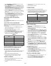
ADJUSTING TONE ARM HEIGHT:
The tone arm height is adjustable between 0 and 6 mm. A HEIGHT
SCALE (13) (in 0.5 mm increments) is provided to aid in an
accurate setting.
1. Unlock the tone arm by turning the ARM LOCK (14) knob
away from the lock position.
2. Look up the cartridge height on Table A and find its
corresponding height scale reading.
3. Turn the HEIGHT ADJUSTMENT RING (12) until the reference
line on the ring is positioned at the correct scale reading.
4. Lock the tone arm by turning the ARM LOCK (14) knob
clockwise until it reaches the lock position.
TABLE A
For example, if the height of the cartridge is 18.5 mm, the ARM
HEIGHT ADJUSTMENT RING (12) reference line should be
positioned between 3 and 4 on the HEIGHT SCALE (13).
INSTALLING THE DUSTCOVER:
1. Hold the dustcover in position, directly above the turntable, and
slide the hinge bases into the holders mounted on the rear
panel.
2. Always raise the dustcover before removal.
3. Avoid opening and closing the dustcover during play.
Undesirable vibration and stylus skipping can result.
UNIT PLACEMENT:
1. Place unit on a flat, vibration free surface. Use the turntable
feet to horizontally stabilize the unit.
2. Try to place the unit as far away from the speakers as
possible.
3. Keep the unit away from direct exposure to the sun, heat,
moisture or dirt.
4. Keep the unit well ventilated.
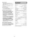
CONNECTIONS:
1. Plug the AC power plug into an appropriate outlet.
2. See Table B for proper connection of the output RCA plugs and
ground connector. Make sure that all the plugs are firmly
plugged into the appropriate jacks. To reduce hum, make sure
the ground lug is firmly connected to the ground screw.
TABLE B
Operating Instructions
BASIC OPERATION:
1. Place a record on the RUBBER MAT (3) which sits on the
PLATTER (2).
2. Select the desired speed by depressing the 33 or 45 SPEED
SELECTOR BUTTON (17).
3. Turn the POWER SWITCH (15) to the “ON” position, at which
point the strobe illuminator (built into the POWER SWITCH (15)
and the speed indicator (for the selected speed) will illuminate.
4. Remove the stylus protector (if applicable to your cartridge).
5. Release the ARM CLAMP (8) found on the ARM REST (9).
6. Push the START STOP BUTTON (16). The turntable PLATTER
(2) will start to spin.
7. Push the CUE LEVER (18) to the “UP” position.
8. Position the tone arm over the desired position on the record
and push the CUE LEVER to the “DOWN” position. The TONE
ARM (5) will slowly lower onto the record at which time play
will begin.
9. When play is over, raise the TONE ARM (5), move it to the
ARM REST (9), and secure it with the ARM CLAMP (8).
10.You now have the option of turning off the power by turning
the POWER SWITCH (15) to the “OFF” position, or stopping
the PLATTER (2) by pushing the START STOP BUTTON (16)
and engaging the electronic brake.
INTERRUPTING PLAY:
1. Pushing the CUE LEVER (18) to the “UP” position will cause
the TONE ARM (5) to lift stopping play.
2. Pushing the CUE LEVER (18) to the “DOWN” position will
cause the TONE ARM (5) to slowly lower onto the record at
the point where play was interrupted.
PLAYING 45 RPM RECORDS:
1. When playing a 45 rpm record with a large center hole, first
place the 45 ADAPTOR (19) on the center spindle.
2. Be sure that the 45 SPEED SELECTOR BUTTON (17) is
pushed and the 45 speed indicator is illuminated.