


Model RM-2 Owner’s Manual
5
STEREO RACK MONITOR
RM-2
CH SEL
DIGITAL
ANALOG
INPUT
+6420
60 12 6 42 0OL52443628 16
-
20
28 7 32016 10 5
-R
MUTEMONO
DIGITAL
0246+L
1628364452 OL024612
20
5101620
- 3728
VU
-
60
[dBFS]
PEAK
PHONES
MIN MAX
RL
STEREO RACK MONITOR
RM-2
CH SEL
DIGITAL
ANALOG
INPUT
+6420
60 12 6 42 0OL52443628 16
-
20
28 7 32016 10 5
-R
MUTEMONO
DIGITAL
0246+L
1628364452 OL024612
20
5101620
- 3728
VU
-
60
[dBFS]
PEAK
PHONES
MIN MAX
RL
STEREO RACK MONITOR
RM-2
CH SEL
DIGITAL
ANALOG
INPUT
+6420
60 12 6 42 0OL52443628 16
-
20
28 7 32016 10 5
-R
MUTEMONO
DIGITAL
0246+L
1628364452 OL024612
20
5101620
- 3728
VU
-
60
[dBFS]
PEAK
PHONES
MIN MAX
RL
STEREO RACK MONITOR
RM-2
CH SEL
DIGITAL
ANALOG
INPUT
+6420
60 12 6 42 0OL52443628 16
-
20
28 7 32016 10 5
-R
MUTEMONO
DIGITAL
0246+L
1628364452 OL024612
20
5101620
- 3728
VU
-
60
[dBFS]
PEAK
PHONES
MIN MAX
RL
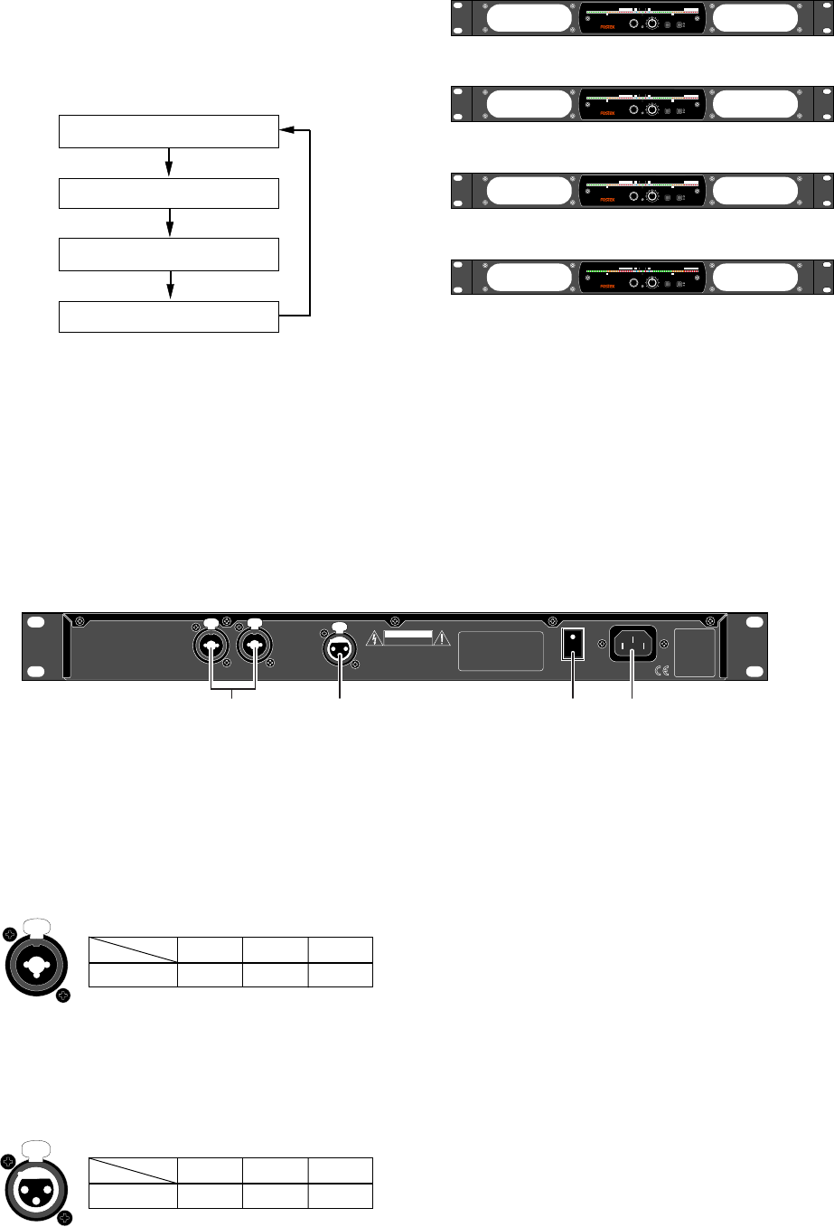
10) [POWER] switch
This switch turns the power on or off.
Each time you turn on the power, the RM-2 is
muted for preventing the noise from being
generated from the speaker units (the "MUTE"
indicator flashes).
11) [AC IN] connector
Connect to the AC outlet using the supplied
power cord.
Make sure that the AC outlet voltage matches
the unit.
RL
ANALOG INPUT
DIGITAL INPUT
CAUTION
AVIS:
RISQUE DE CHOC ELECTRIQUE
NE PAS OUVRIR
WARNING:
TO REDUCE THE RISK OF FIRE OR ELECTRIC
SHOCK, DO NOT EXPOSE THIS EQUIPMENT
TO RAIN OR MOISTURE.
AC IN
ON
POWER
OFF
11108
9
8) [ANALOG INPUT] connectors (XLR / 1/4" combi-
jacks)
You can connect an XLR-3-12C connector or
1/4" plug to each of these combi-jack type
[ANALOG INPUT] connectors (you cannot
insert both together). Each connector accepts a
+4 dBu analog signal via XLR connection or a
-10 dBV analog signal via 1/4" connection.
1
2
3
1
2
3
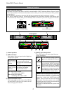
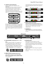
5) [CH SEL] (channel select) key
This key switches the channel(s) to be
monitored.
Each press of the key switches the channel(s)
in the following order (by default when
turning on the power, "stereo" is selected).
The current selection is shown by the
indicators in the status information section (see
page 6 for the indication of channel selection).
Stereo
Mono (L+R)
Mono (L only)
Mono (R only)
6) Monitor output level controls
These dual concentric controls adjust the
speaker output (or headphones output) levels.
The outer control adjusts the left channel level,
while the inner control adjusts the right
channel level.
7) PHONES jack
This jack is used for connecting headphones.
When a plug is inserted, the internal speakers
are cut.
<Rear panel>
9) [DIGITAL INPUT] connector (XLR connector)
This connector accepts an AES/EBU digital
signal at the sampling frequency within the 44.1
kHz to 96 kHz range. You can connect an XLR-
3-12C connector.
By long press of the [CH SEL] key, you can mute
the unit, while the [MUTE] indicator flashes (this
is called "user mute"). Pressing the [CH SEL] key
again release muting and the [MUTE] indicator
turns off. See page 6 for the user mute func-
tion.
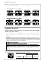
The following shows which signal is output from
each internal speaker unit for each channel se-
lection.
When "Stereo" is selected
When "Mono (L+R)" is selected
When "Mono (L only)" is selected
When "Mono (R only)" is selected
L
R
L+R
L+R
LL
RR
XLR
HOT (+) COLD (-)
Ground
Pin 2
Pin 3 Pin 1
XLR
HOT (+) COLD (-)
Ground
Pin 2
Pin 3 Pin 1