


1
4 5
2 3 4 5 6
8
7
9
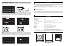
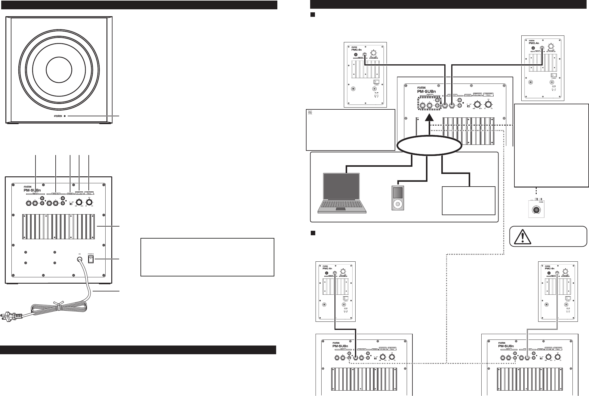
Names & Functions
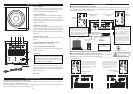
Connecting PM-SUBn to PM0.4n (x 2 units)
Connect a stereo signal source from PC/portable music player to the PM-SUBn INPUT terminals (L, R). Next,
connect the PM-SUBn THRU terminal (L, R) to a pair of PM0.4n INPUT terminals. The connection is the same
when PM0.5n is used as a main speaker system.
Provided phone-phone
cable (white)
PM0.4n
(L channel)
Provided phone-phone
cable (red)
PM0.4n
(R channel)
THRU OUT terminals
The THRU OUT terminals output signals
fed to the INPUT terminals regardless of
the PM-SUBn power switch on/off
condition. If the phone plug is connected to
the THRU OUT PHONE jack, the signal
fed to the THRU OUT RCA jack is cut.
Provided stereo mini
-RCA cable
PC
Provided stereo mini
-RCA cable
Portable music player
Provided RCA
pin cable
Connection Method
When a volume controller is used;
1.
2.
3.
Connect a signal source to PC-1
using a stereo mini cable.
Connect the PC-1’s RCA OUT
(L, R) to the PM-SUBn RCA
INPUT (L, R) using the RCA pin
cable provided with PC-1.
Referring to the explanation
mentioned in the page 7 of this
manual, adjust the PM-SUBn
SUB WOOFER volume and the
PM0.4n volume. PC-1 can adjust
both the P M-SUBn and the
PM0.4n volume level.
PC-1 volume controller
Make sure to power off
the amplifier and then
connect the cables.
Connecting PM-SUBn (x 2 units) to PM0.4n (x 2 units)
Using 2 units of PM-SUBn improves the low sound massiveness. Also L and
R independent signals allow more realistic sound reproduction.
Connect a signal source L channel
output to the PM-SUBn INPUT
(L) terminal. Then, Connect the
PM-SUBn THRU OUT (L) to the
input terminal of PM0.4n placed
on the L channel side.
Connect a signal source R channel
output to the PM-SUBn INPUT
(R) terminal. Then, Connect the
PM-SUBn THRU OUT (R) to the
input terminal of PM0.4n placed
on the R channel side.
PM0.4n placed on the L side
PM0.4n placed on the R side
Provided phone-phone
cable (white)
Provided phone-phone
cable (red)
1. Power indicator
It indicates the built-in power amplifier power on/off
condition. It is lit when turning on the [POWER] switch.
It is unlit when turning off the [POWER] switch.
2. [INPUT] terminals
A signal source output from PC/portable music player or
a line level signal output from an amplifier is connected
to the [INPUT] terminals. If the signal source is
connected to the PHONE jack, the signal source fed to
the RCA terminal is cut.
3. [THRU OUT] terminal
A signal fed to the [INPUT] terminal is output from the
[THRU OUT] terminal regardless of the power switch
on/off condition. If the signal is taken out from the
PHONE terminal, the signal source output from the RCA
terminal is cut.
4. [PHASE 0º, 180º ] switch
This switch changes the sub woofer phase between 0º
and 180º.
5. [SUB WOOFER VOLUME] adjusting knob
It adjusts the output level of PM-SUBn.
6. [LOW-PASS FREQ.] adjusting knob
It adjusts the cross-over frequency of the low-pass filter
from 50 to 150 Hz.
7. Heat sink
8. [POWER] switch
Power off and on the built-in power amplifier. When
powering off/on, fully turn down both the PM-SUBn
[SUB WOOFER VOLUME] and the connected powered
speaker output volume.
9. AC cable
Caution When Cleaning
Cleaning the front baffle/enclosure with caution.
• If there are marks attached on the enclosure surface, squeeze a soft cloth steeped into a watered-down neutral
detergent and wipe the surface with the cloth.
• If dust is attached on the speaker unit surface, sweep it lightly using a duster. Do not touch the unit surface
directly with your hand or clean it with a wet wiping cloth.
<CAUTION>
When this unit is used for a long time, the heat sink
heats up. Do not touch it with a bare hand. You
might suffer a burn. Please place the unit in order
not to bother the heat sink radiation.
Connect one of the
music source.
Amplifier /
Recording mixer, etc.