


5
TYPE: PR 308
CAUTION: CHASSIS SURFACE HOT
WARNING: TO REDUCE THE RISK OF FIRE
OR ELECTRIC SHOCK , DO NOT EXPOSE THIS
EQUIPMENT TO RAIN OR MOISTURE
AVIS: RISQUE DE CHOC ELECTRIQUE NE PAS OUVRIR
ATTENTION: SUPERFICIE DE CHASSIS CHAUDE
RETURN SEND
PATCH POINT
BALANCED INPUTS
OUTPUTS
500W
2Ω
MIN
TOTAL
CLASS 2 WIRING
PARALLEL SPKR. JACKS
ATTENTION:
UTILISER UN FUSIBLE DE
RECHANGE DE MEME
TYPE ET CALIBRE
CAUTION:
TO REDUCE THE RISK OF
FIRE, REPLACE FUSE WITH
SAME TYPE AND RATING
900W
SERIAL NUMBER
F10A
250V
FUSE
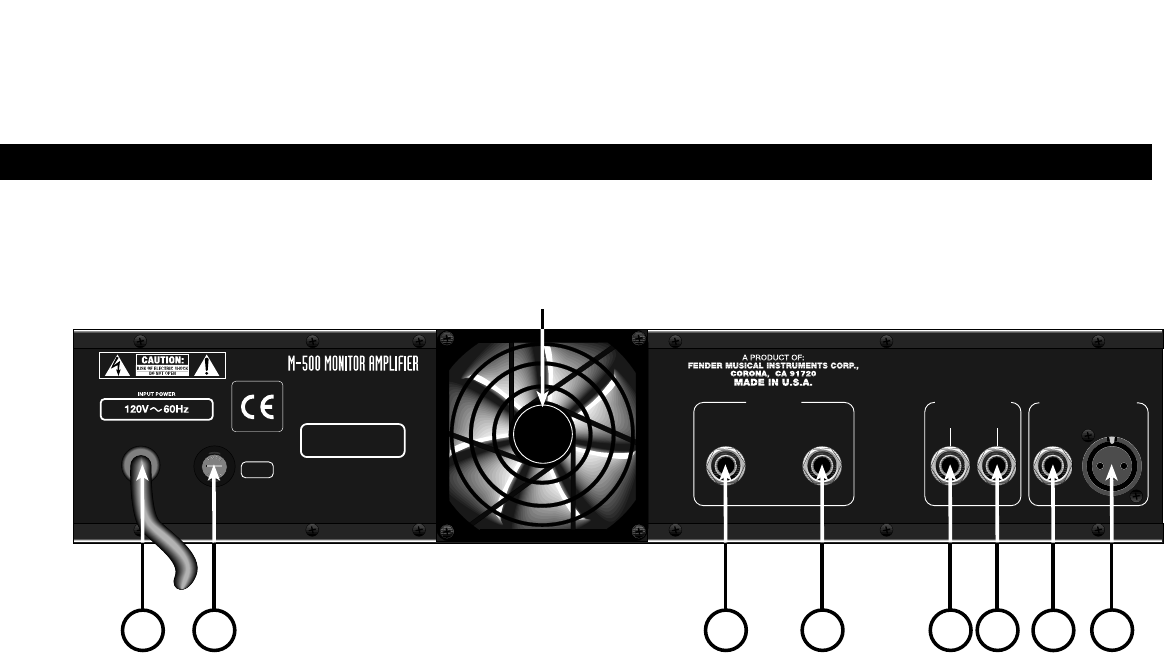
DO NOT BLOCK FAN OPENING
JK L
M
N
O
O
L
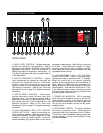
H. PEAK LED INDICATOR - The red Peak LED
Indicator illuminates when the output voltage of the
amplifier reaches clipping (maximum output voltage).
The threshold for the peak indicator automatically
adjusts for load impedance and supply voltage
variations.
I. POWER SWITCH - The power switch turns the
unit on and off. The LED (item F) is illuminated when
the amplifier is turned on and main voltage is present.
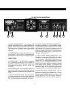
REAR PANEL
J. POWER CORD - The SPL-M500 is equipped
with a grounding type supply cord to reduce the
possibility of shock hazard. Be sure to connect it to
a grounded AC receptacle. DO NOT ALTER THE
AC PLUG.
K. EXTERNAL FUSE - When necessary, replace the
external fuse ONLY with one of the same type and
rating as shown on the label next to the external fuse
holder.
L. OUTPUT SPEAKER JACKS - Two parallel-wired,
1/4"output connectors are provided capable of
providing 500 Watts of power into a 2Ω minimum load
total. (One 2Ω speaker or two speakers at 4Ω each).
M. PATCH POINT RETURN CONNECTOR -
Provides the possibility of using the power amplifier
by bypassing the preamp section of the unit. When
this connector is used, the preamp is totally
disconnected from the power amplifier section. If
nothing is plugged into this jack, it normally takes its
signal from the preamp output, via the PATCH POINT
SEND
jack. (See section N).
N. PATCH POINT SEND CONNECTOR - This
connection can be used with the patch point return
connector, if further signal processing by an external
unit is desired. Processing could include the
insertion of a 1/3 octave graphic equalizer for tonal
shaping, an external compressor/limiter and/or the
insertion of an active electronic crossover network
for bi-amped monitor systems. The output of this
jack is normally tied to the patch point return
connector. Using this connector will not disconnect
the preamp section from the power amplifier section.
O. BALANCED INPUT CONNECTORS - This unit
provides two types of input connectors: a 1/4 inch
TRS and an XLR female connector. The 1/4 inch
TRS connector polarities are: tip (+), ring (-), and
sleeve (ground). The XLR female connector
polarities are: pin 2 (+), pin 3 (-), and pin 1 (ground).