


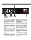
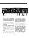
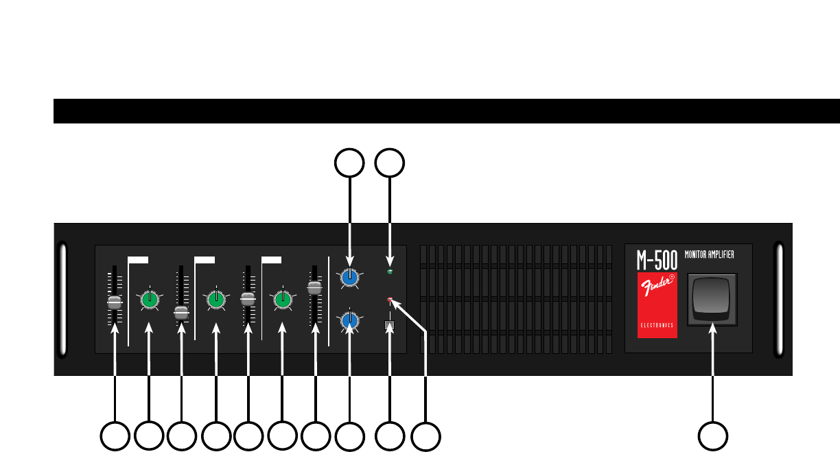
A. INPUT LEVEL CONTROL - Variable attenuator
controls the amplifier's input sensitivity. Control
settings can vary between +8dB (fully up) and infinite
attenuation (fully down). At the full up position, a
360mV input signal is required for rated output. At
0, a 360mV input signal will yield an output power of
1/8th rated power.
B. NOTCH FREQUENCY CONTROL - Higher
notch frequencies are selected as the knobs are
rotated in the clockwise direction. Each knob
covers a specified frequency range, but two
adjacent knobs do have overlapped frequencies.
This feature is intentional. Refer to the "Hints and
Precautions" found on page 7 for details concerning
this feature.
C. NOTCH DEPTH CONTROL - These sliders
provide attenuation control for each notch filter
frequency band. At the highest position, 0dB of
attenuation is obtained. At the lowest position, they
can provide more than 25 dB of attenuation at the
selected frequency. Refer to the "Hints and
Precautions" found on page 7 for details concerning
this feature.
D. HIGH FREQUENCY ROLL OFF CONTROL
(LOW PASS FILTER) - Useful for smoothing out
"edgy" sounding speakers. When this knob is fully in
its clockwise position, all signals below 30 kHz are
allowed to enter the power amplifier. If set fully
counter clockwise, only signals below 2.5 kHz will be
permitted to pass through. Start with this control set
at 30 kHz. If the performers complain of "edgy"
sounding monitors and want smoother sounding
ones, rotate this control counter clockwise until they
are pleased with the sound.
E. LOW FREQUENCY ROLL OFF CONTROL
(HIGH PASS FILTER) - Useful for removing rumble
(mechanical noise) or resonance and L.F. leakage.
When this knob is fully in its counter clockwise
position, all input signals above 12Hz are allowed to
pass. When it is positioned fully clockwise, only
frequencies above 150 Hz are permitted to enter the
power amplifier. Start with this control set at 12 Hz.
If the performers want crisper sounding sounding
monitors slowly rotate this control clockwise until
they are pleased with the sound.
F. POWER LED INDICATOR - LED is illuminated
when the monitor amplifier is turned on, and the AC
mains voltage is present. If the indicator does not
light when the power switch is turned on (and does
not trip the circuit breaker), check the AC power
supply and fuse.
G. DELTACOMP
™
SWITCH - This switch activates
the internal compressor circuit. Peak clipping is
minimized when the compressor circuit is active.
This will also "clamp" feedback, helping protect your
monitor speakers. During normal operation, keep
this switch engaged.
4
225
50 500
70
NOTCH DEPTH
LOW
INPUT LEVEL
+6dB
0dB
- 00
430
2k
400 5k
700
NOTCH DEPTH
MID
4k
4k
800 10k
NOTCH DEPTH
HIGH
9k1k
60
FLAT 150
12 016
LOW FREQ. ROLLOFF
12k
2k FLAT
35k4k
HIGH FREQ. ROLLOFF
POWER
DELTACOMP
TM
0dB
-6
-3
-12
0dB
-6
-3
-12
0dB
-6
-3
-12
FREQUENCY FREQUENCY FREQUENCY
FREQUENCY FREQUENCY FREQUENCY
MAX. MAX. MAX.
FEEDBACK CONTROL FILTER
A
BBB
C
CC
D
E
F
G
H
I
POWER
ON
DESCRIPTION OF FEATURES
FRONT PANEL