


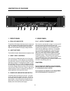
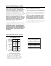
1. FRONT PANEL
A - PEAK LED INDICATOR
The red Peak LED Indicator illuminates when the output volt-
age of the amplifier reaches clipping (maximum output volt-
age). The threshold for the peak indicator automatically
adjusts for load impedance and supply voltage variations.
B - LIMIT SWITCHES
The Limit Switch is used to defeat the internal compressor circuits.
C - INPUT LEVEL CONTROLS
Two continuously variable attenuators control the ampli-
fier's input sensitivity. Control settings can vary between
zero attenuation (maximum clockwise rotation) and infinite
attenuation (maximum counterclockwise rotation). At the
full clockwise rotation, a +1.8 dBV input signal is required
for rated output. Each gain control is independent except
for the Mono Bridge mode where Channel A is the active
control and the Channel B control is inactive. Refer to the
Amplifier Operation section for additional information on
proper adjustment of the input level controls.
D - POWER LED INDICATOR AND SWITCH
The power switch turns the unit on and off. To turn the
unit on, push the power switch to the right. The LED is
illuminated when the amplifier is turned on and main volt-
age is present. If this indicator does not light when the
power switch is turned on (and does not trip the circuit
breaker), then check the AC power supply.
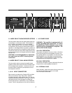
2. REAR PANEL
E & F - OUTPUT CONNECTORS
Each channel is provided with a single 1/4" phone jack (E)
and a pair of five-way binding posts (F) which will
accommodate a single pair of dual banana plugs (multiple
stacked banana plugs are not recommended as they
tend to fall out), spade lugs or bare wire. If the speaker
wire is terminated with spade lugs, make sure that the
lugs are tin or gold plated brass or copper, not plated
steel. Non-linear contact resistance phenomena will
degrade the sonic integrity of any amplifier at the speak-
er/amplifier interface. The Channel A and Channel B
outputs are spaced on 0.75 inch (19 mm) centers so that
one "double banana plug" can be used for bridged
operation. During performance verification measurements,
use the five-way binding posts only.
CAUTION:
Do not operate the amplifier in the two channel
(stereo) mode with a load impedance of less than
4 Ω connected to either channel.
Do not operate the amplifier in the Bridged Mode
with a load impedance of less than 8 Ω.
3
SPL 6000
LEFT •CHANNEL A
RIGHT•CHANNEL B
PROFESSIONAL STEREO POWER AMPLIFIER
POWER
PEAK
LIMIT
PEAK
LIMIT
MAX
MIN
MAX
MIN
OFF
ON
OFF
ON
ELECTRONICS
A
B
C
C
A
D
D
B
DESCRIPTION OF FEATURES