


8
The C51 contains five identical channel pairs
(bass/treble) of audio amplification. Unless
otherwise stated, this section refers to one
channel only.
Input connections
Two full-inputs are provided for each channel:
balanced(XLR-3F)andunbalanced(gold-
plated phono). The active input is selected
with a slide switch.
The audio connections should be made with
highqualityaudiophonoleadsorXLRleads.
Trigger input
The unit is designed to be switched in and
out of standby by means of the application of
a trigger voltage via this 3.5 mm mono jack
socket. The application of an AC or DC voltage
between 5 and 30 volts will turn the unit on
(ie bring it out of standby). Removing the
voltage will return the unit to standby. Ensure
that the trigger source is configured to provide
a voltage within this range when the unit is
required to be switched on.
Output connections
Connect the cables from the rear-panel output
terminals to the speaker units. Be sure to
observe correct polarity and the source and
destination of each channel.
Note that these terminals can develop
significant voltages/current-passing capability
when the C51 is powered up and being
fed with an active signal. Ensure that
connections are made with the power
disconnected from the unit.
You can connect five Meridian Active
Installation Loudspeakers (such as the A320,
A330, A350, or A200Z) to the C51. The C51
is designed specifically for use with Meridian
Active Installation Loudspeakers, each of which
is supplied with the appropriate crossover
module. As a result the unit cannot be used
with other loudspeakers.
• ConnecteachMeridianActiveInstallation
Loudspeaker to the appropriate outputs, using
two pairs of speaker cables for each speaker
connected to the BASS + and -, and the
TWEETER + and - terminals.
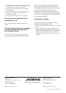
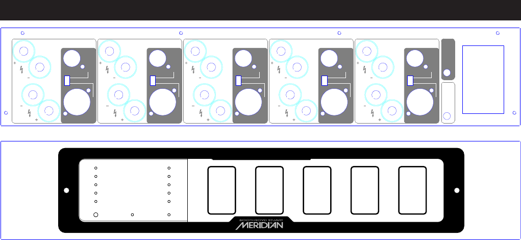
• Plugthecrossovermodulesuppliedwith
each Active Installation Loudspeaker into the
appropriate crossover bay on the front panel
of the C51, and re-fit the acrylic cover. Ensure
that the card is correctlly seated and that the
correct card for the speaker is in the appropriate
slot. Each crossover card includes indicator
lights that show the presence of power and, by
their colour combination, indicate the type of
speaker for which the card is designed.
• Connecttheinputforeachchanneltothe
appropriate CHANNEL 1 to 5 INPUT, using either
the BALANCED or UNBALANCED input, and
setting each INPUT switch accordingly.
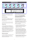
FAN OUTPUT
MERIDIAN
CONTROLLED
Stand By Hot
Channel 1
Channel 2
Channel 3
Channel 4
Channel 5
Bass Treble
TWEETER
UNBALANCED
BALANCED
CHANNEL 5
OUTPUT
INPUT
BASS
ONOFF
CAUTION REPLACE WITH SAME TYPE FUSE
T10AH for 100-120V ac ~
POWER INPUT ~50-60Hz 30-1200VA MAX
5 - 30V ac or dc
TRIGGER INPUT
TWEETER
UNBALANCED
BALANCED
CHANNEL 4
OUTPUT
INPUT
BASS
TWEETER
UNBALANCED
BALANCED
CHANNEL 3
OUTPUT
INPUT
BASS
TWEETER
UNBALANCED
BALANCED
CHANNEL 2
OUTPUT
INPUT
BASS
TWEETER
UNBALANCED
BALANCED
CHANNEL 1
OUTPUT
INPUT
BASS
C51 Active Speaker Power Unit
Crossover
Channel 5
Crossover
Channel 4
Crossover
Channel 3
Crossover
Channel 2
Crossover
Channel 1
C51 Rear Panel (above) and front panel with acrylic cover in place (below)
CONNECTING THE C51