


Extron TP Transmitters • Installation and Operation
Extron TP Transmitters • Installation and Operation
Installation and Operation, cont’d
Preparing the site and installing the mud ring or wall box
The TP T 468 is mounted into a wall or furniture. Follow the
instructions appropriate to the mounting option you have
selected. Templates for optional faceplates are not included in
this manual.
CAUTION
The transmitter must be installed into an
Underwriters Laboratories (UL) approved electrical
wall box.
Choose a location that allows cable runs without interference.
Allow enough depth for both the wall box and the cables. You
may need to install the cables into the wall, furniture, or
conduits before installing the transmitter.
The installation must conform to national and local electrical
codes and to the equipment’s size requirements. An actual-size
cut-out template is provided in appendix A of this manual.
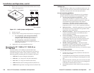
Installation using a UL listed wall box (available from Extron) is
recommended for most mounting options, but the included
mud rings can be used instead. All wall boxes must be at least
2.5" (6.4 cm) deep.
Before using the mud rings, verify that the installation
conforms to national and local electrical codes.
1. Select and cut out the appropriate template for your
installation type:
• If you are using a mud ring, use the template
provided with the mud ring. Cut out the indicated
center portion.
• If you are using a wall box, cut out or make a 100%
size photocopy of the template in appendix A that
corresponds to the faceplate you are using, and cut
out the center portion as indicated on the template.
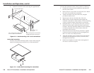
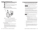
2. Place the template (or the wall box or mud ring) against
the installation surface, and mark the guidelines for the
opening on the wall or furniture.
3. Cut out the wall or furniture material from the marked
area.
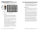
4. Check the opening size by inserting the wall box, mud
ring, or transmitter into the opening. The box or mud ring
(if used) and/or transmitter should fit easily into the
opening. Enlarge or smooth the edges of the opening if
needed.
2-132-12
9
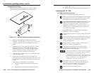
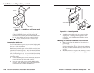
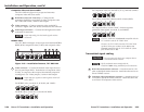
Install the desired AAPs on the transmitter. See
“Mounting the optional AAP devices,” later in this
chapter.
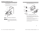
10
Mount the transmitter into the electrical box or to the mud
ring. If using a wall box, see “Mounting the transmitter to
the mud ring or wall box,” later in this chapter.
11
Restore power to the devices.
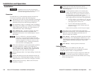
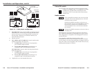
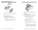
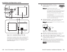
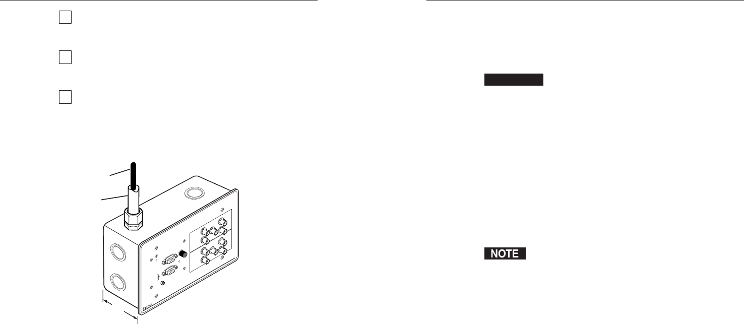
UL guidelines for wall box installation
The following Underwriters Laboratories (UL) requirements
pertain to the installation of the TP T 468 into a wall or furniture
(figure 2-6).
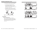
MONITOR
H. SHIFT
AUDIO
MIN/MAX
TP T 468
INPUT
TP T 468
2.5"
Installation
Cable
Conduit
N
O
M
O
N
ITO
R
M
O
N
IT
O
R
Figure 2-6 — TP T 468 in a four-gang wall box
1. This unit is not to be connected to a centralized DC power
source or used beyond their rated voltage range.
2. This unit must be installed in UL listed junction boxes.
3. This unit must be installed with conduit in accordance
with the National Electrical Code.
Euro Channel models
The TP T 468 is available in a Euro Channel (EC) version (see
appendix A for part numbers).
The front and rear panel features, cabling requirements, and
testing/troubleshooting procedures are identical to the
descriptions shown in chapter 2, Installation and Operation, for
the non-EC models. See Euro Channel transmitter installation in
this appendix for the EC transmitter model installation
instructions.