


Extron TP Transmitters • Installation and Operation
Extron TP Transmitters • Installation and Operation
Installation and Operation, cont’d
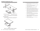
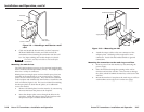
Tabletop use
Four self-adhesive rubber feet are included with the unit. For
tabletop use, affix one foot at each corner of the bottom of the
transmitter, and place the unit in the desired location.
UL rack mounting guidelines
The following Underwriters Laboratories (UL) guidelines
pertain to the safe installation of the equipment in a rack.
1. Elevated operating ambient temperature — If the
equipment is installed in a closed or multi-unit rack
assembly, the operating ambient temperature of the rack
environment may be greater than room ambient
temperature. Therefore, install the equipment in an
environment compatible with the maximum ambient
temperature (Tma = +113 °F, +45 °C) specified by Extron.
2. Reduced air flow — Install the equipment in a rack so that
the amount of air flow required for safe operation of the
equipment is not compromised.
3. Mechanical loading — Mount the equipment in the rack
so that a hazardous condition is not achieved due to
uneven mechanical loading.
4. Circuit overloading — Connect the equipment to the
supply circuit and consider the effect that circuit
overloading might have on overcurrent protection and
supply wiring. Also consider equipment nameplate
ratings when addressing this concern.
5. Reliable earthing (grounding) — Maintain reliable
grounding of rack-mounted equipment. Pay particular
attention to supply connections other than direct
connections to the branch circuit (e.g., use of power strips).
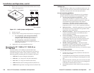
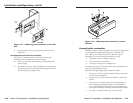
Rack mounting procedure
To mount the transmitter on a 9.5" deep rack shelf,
1. If rubber feet were previously attached to the bottom of
the unit, remove them.
2. Fit the RSM 100 mounting bracket around the transmitter
and attach it to the unit using one mounting hole on each
end.
3. Mount the bracket containing the unit onto the rack shelf,
using two 4-40 x 3/16" screws in the two mounting holes
in the bottom of the bracket to secure it.
4. Install blank panel(s) or other unit(s) on the rack shelf as
desired.
2-72-6
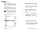
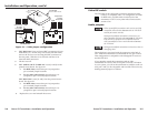
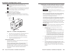
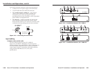
1. Remove the two screws on each side and the screw on top
of the cover (figure 2-2).
PC
H-SHIFT
TP T 15HD AV
AUDIO
VIDEO
AUDIO
L
R
BUFFERED
COMPUTER
INPUT
LOCAL MONITOR
ID PIN 4
ID PIN 11
Wire Pair
3&6*
* TPX compatible
Wire Pair
7&8
TP T 15HD AV
Remove (5)
Screws
Lift Cover
straight up
J6
J7
TP T 15HD AV
1
1
Figure 2-2 — Audio jumper configuration
2. Lift the cover off.
3. Locate J6 and J7 on the printed circuit board. See figure 2-2.
a. For compatibility with redesigned (modified)
receivers and the TPX 88 A, ensure that pin 1 is
jumpered to pin 2 on both jumper locations.
b. For compatibility with older (unmodified)
receivers, ensure that pin 2 is jumpered to pin 3 on
both jumper locations.
4. Replace the cover and reinstall the screws.
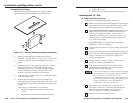
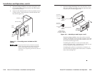
Mounting the TP T 15HD A, TP T 15HD AV, or
TP T BNC DA4
The TP T 15HD A, TP T 15HD AV, and TP T BNC DA4
transmitters can be set on a table; mounted on a rack shelf; or
mounted through or under a desk, podium, or tabletop. The
following optional mounting kits are available for the series:
• RSM 100 TP rack mounting kit (#60-604-02)
• RSB 129 1U, 9.5" deep basic rack shelf (#60-604-02)
• RSU 129 1U, 9.5" deep rack shelf kit (#60-190-01)
• MBU 125 under-desk mounting bracket kit (#70-077-01)
• MBD 129 through-desk mounting bracket kit (#70-077-02)