


Extron TP Transmitters • Installation and Operation
Extron TP Transmitters • Installation and Operation
Installation and Operation, cont’d
TP T 15HD A
TP R BNC A
TP T 15HD A
H-
SHIFT
BUFFEREDCOMPUTER
INPUT
AUDIO
ID PIN 4
ID PIN 11
LOCAL MONITOR
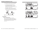
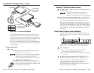
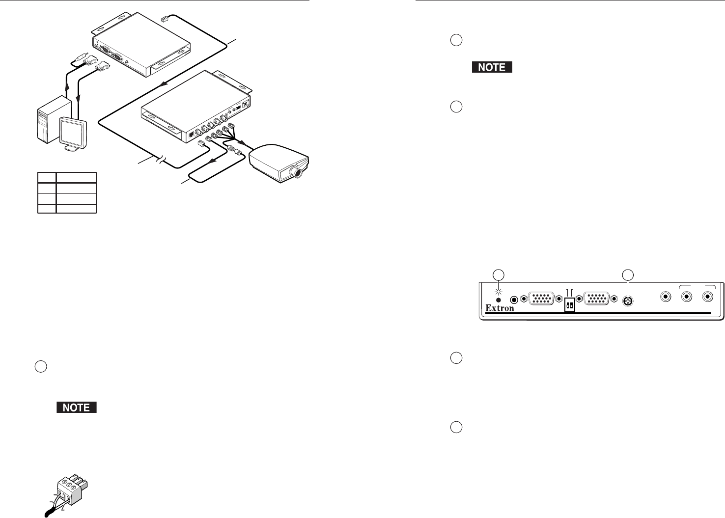
PC Computer
CAT 5 UTP Cable
Audio
LCD Projector
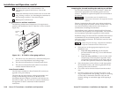
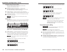
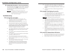
... THEN insert a four foot
extension cable to equalize
TP skew for red video.
IF cable measurement
indicates that the pair
with wires
1 and 2
is
four feet shorter than
the other pairs...
R
GB
IN
P
UT
R
G
B
O
UT
PU
T
R
G
B
H/H
V
V
A
A
UD
IO
L
R
B
SOG
C SYNC
P
OW
ER
15
V .5A
DC
L
R
Pair RGB video
1, 2 Red
4, 5 Green
7, 8 Blue
Figure 2-20 — Pair skew equalization
If UTP cable test measurement cannot be done, pair skew can
still be equalized by viewing a test pattern with a critical eye.
Examine the test pattern for loss of horizontal registration and,
through a process of trial and error, equalize any pair skew with
coax extensions on the red, green, and/or blue outputs.
Extron skew compensation coax cables are available in lengths
of 2 through 20 feet (61 cm through 6.1 meters). See appendix A
for part numbers.
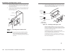
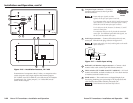
Power connector
12
Power
TP T BNC DA4 — Plug the external 15V power supply
into this captive screw connector.
If the distance between the transmitter and receiver is too
great for the receiver to power the transmitter, the video
image will be missing, distorted, or noisy, or the
receiver’s Manual/Auto LED will flash. The transmitter
requires a local 15V power supply.
TP T 15HD A and TP T 15 HD AV— If desired or for
distances over 300' (91.4 m), plug an external 15 VDC
power supply into this captive screw connector. Wire
the connector as shown at left.
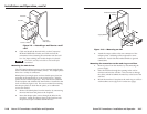
Unique TP T 468 front panel features
13
Faceplate screws — These screws secure the faceplate to the rest
of the transmitter.
Do not remove these faceplate screws while the
transmitter is attached to the wall or the detached
transmitter circuit board may fall down inside the wall.
14
Opening for Architectural Adapter Plates — The TP T 468 can
have up to four optional adapter plates attached here at one
time. The adapter plates allow for a variety of connectors.
Blank plates (two single-space and one double-space plate) are
included on the transmitter to cover unused spaces. Adapter
plates must be ordered separately. They also must be attached
to the faceplate and cabled before the interface is installed in the
wall or furniture. See “Mounting the AAP devices,” earlier in
this chapter.
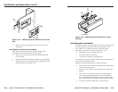
Front Panel Control and Indicators
All of the transmitters have front panel Power indicators. In
addition, the TP T 15HD A and TP T 15HD AV have horizontal
shift control.
TP T 15HD AV
PC
H-SHIFT
BUFFEREDCOMPUTER
INPUT
AUDIO
ID PIN 4
LOCAL MONITOR
VIDEO
AUDIO
L
R
ID PIN 11
1 2
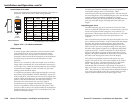
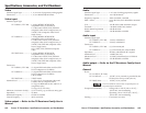
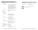
Figure 2-21 — TP T 15HD AV control and indicator
1
Power/signal LED
Amber — Indicates that power is applied, but that the
transmitter is not connected to a receiver.
Green — Indicates that the transmitter is properly connected to
a receiver.
2
H. Shift control (TP T 15HD A and TP T 15HD AV) — This
front panel knob adjusts the side-to-side image placement.
The H. Shift control is a 12-turn potentiometer with a soft
mechanical stop at the high or low end. When you have
reached the high or low end of the adjustment, the
potentiometer makes a clicking sound as you turn it, and no
change is apparent on the display.
Return
N/C
+15V
2-292-28