


Extron TP Transmitters • Specifications, Accessories, and Part NumbersExtron TP Transmitters • Specifications, Accessories, and Part Numbers
Specifications, Accessories, and Part Numbers, cont’d
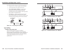
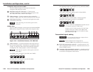
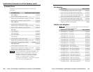
2 - BNC
Blank Plate (no connector)
Single Space
Double Space
Blank Plate (no connector)
5 - BNC (Double)
2 - RJ-11
1 - 3-pin XLR Connector
2 - RCA to Solder Cups
3 - RCA to Solder Cups
2 - S-video
2 - F Connectors
1 - D-9 Pass Through Connector
1 - HD-15 Pass Through Connector
2 - 1/4" Stereo Phono
2 - 3.5mm Stereo Mini
3 - BNC
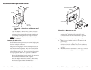
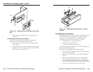
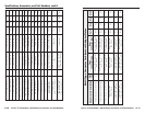
Figure A-1 — Architectural adapter plates
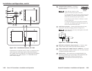
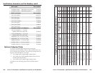
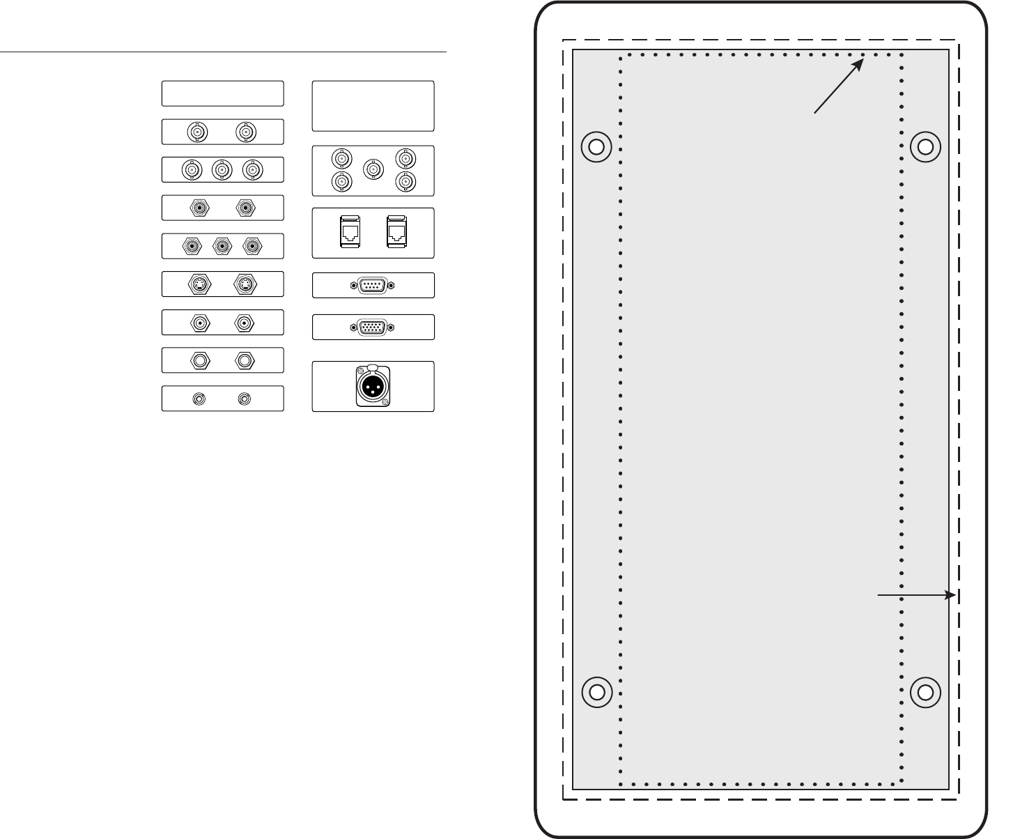
TP T 468 Template
The following template is actual size. It also includes the
recommended 0.1" (0.25 cm) clearance on all sides of the
electrical wall box to allow room for raised area surrounding the
knockout.
The dashed line on the template indicates the cut-out area for
installing a wall box. If you plan to install the TP T 468 without
a wall box, use the smaller cut-out area indicated by the dotted
lines.
Use the following template as a guide for cutting a hole in a
wall or furniture for the 4-gang size electrical box in order to
install the transmitter.
A-12 A-13
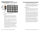
The light gray area represents the layout of the electrical box
(3.75" H x 7.38" W / 9.53 cm H x 18.75 cm W)
against the rear of the TP T 468 front panel.
The dashed line indicates the cut-out area:
(3.95" H x 7.58" W / 10.03 cm H x 19.25 cm W)
for installing the electrical wall box.
To install the interface without a wall box,
use the cut-out area (2.80" H x 7.275" W /
7.11 cm H x 0.7 cm W)
indicated by the dotted line.
TP T 468 4-gang Cut-out Template