Extron TP Transmitters • Installation and Operation
Extron TP Transmitters • Installation and Operation
Installation and Operation, cont’d
c. Tighten the screws.
d. Replace the unit inside the surface (repeat step 4).
Installing the TP T 468
TP T 468 Installation Overview
To install a TP T 468 transmitter, follow these steps:
1
Disconnect power from all of the equipment, including the
video source(s) (such as computers or DVD players), the
transmitter, the receiver, and the output display(s).
2
For non-Euro Channel (EC) versions, prepare the site: cut
a hole in the wall/furniture, install the electrical box or
mud ring, and prepare the cables. Instructions are
included in this manual and/or with the wall box. See
“Preparing the site and installing the mud ring or wall
box,” later in this chapter.
For the EC versions, see “Euro Channel transmitter
installation,” later in this chapter.
3
Connect the input cables. See “Input cabling,” later in this
chapter.
4
Connect the cable(s) between the transmitter(s) and the TP
receiver(s). See “Transmitted signal cabling,” later in this
chapter , and refer to the TP Receivers Family User’s
Manual, part #68-547-01.
5
Configure the TP receiver(s). Refer to the TP Receivers
Family User’s Manual, part #68-547-01.
6
Connect power cords to the TP receiver(s), the TP
transmitter(s) (if applicable), and turn on the video
source(s) and the output display(s).
The TP T 468 includes a 15 VDC external power supply.
The transmitter also receives power from the associated
Extron TP receiver via the TP cable. Extron
recommends using the local power supply; however, the
TP T 468 may not require a local power supply for cable
lengths of 300’ (91.4 m) or less. If problems are
encountered, use the local power supply.
7
Adjust the picture controls on the front panel of the
transmitter and receiver. See Front Panel Control and
Indicators, later in this chapter, and refer to the TP
Receivers Family User’s Manual, part #68-547-01.
8
Disconnect power from all the devices.
2-11
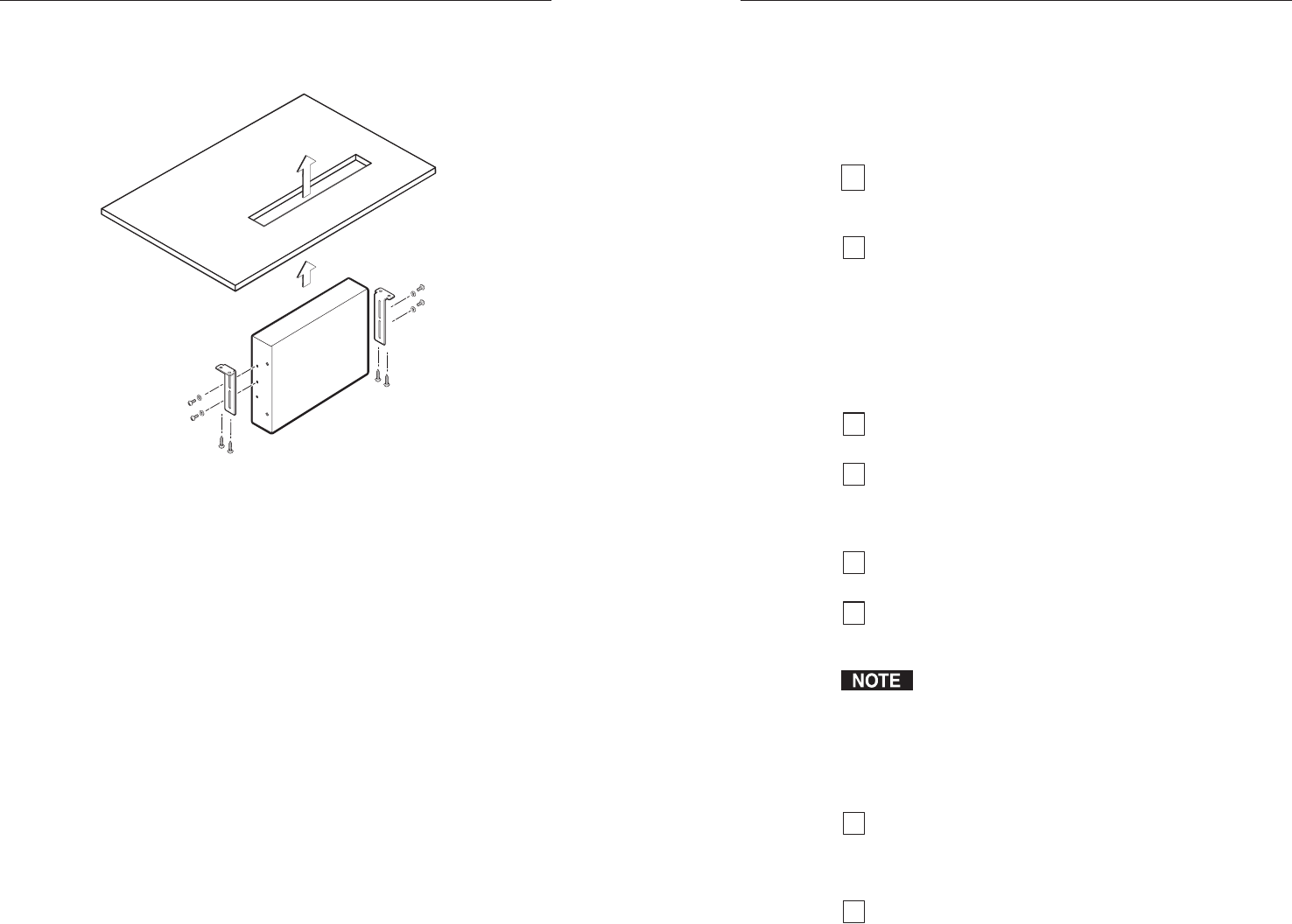
Through-desk mounting
Mount the transmitter through a desk or table, using the
optional through-desk mounting kit (part #70-077-02).
Figure 2-5 — Through-desk mounting the transmitter
1. Mark the opening through which the unit will be
mounted — approximately 1.2" by 6.9" (3.0 cm by 17.5 cm).
2. Cut out the material from the installation area with a
jigsaw.
3. Drill pilot holes 1/4" (6.4 mm) deep and 3/32" (2 mm) in
diameter in the desk or table at the locations of the
mounting bracket screws. The holes should be drilled
from the underside or inside (concealed side) of the
furniture where the transmitter will be located.
4. Using the four provided wood screws, attach the brackets
to the mounting surface.
5. Slide the unit up and down or back and forth in the
mounting brackets until the front panel of the unit is at the
desired height. Tighten the screws that secure the bracket
in place.
If the screws are inaccessible to a screwdriver,
a. Mark the location of the brackets relative to the
screws.
b. Remove the transmitter from inside the furniture.
2-10


