


RGB 109xi and RGB 112xi • Installation
Controls and Installation, cont’d
2-4
3
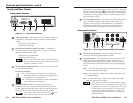
DIP Switch — Controls sync on green output, Digital Display
Sync Processing, and serration pulse removal.
1 — SOG (sync on green output)
On — If this switch is set to On (up), the interface
outputs sync on green.
Off — If this switch is set to Off (down), output is
RGBS or RGBHV, depending on how the interface
and projector are cabled.
2 — DDSP (Digital Display Sync Processing)
On — If this switch is set to On (up), the interface
does not perform sync processing. This may be
necessary for digital display devices, such as LCD,
DLP, and plasma displays.
Off — If this switch is set to Off (down), the interface
performs sync processing operations, such as
horizontal shift, using Extron’s ADSP.
Turning on the DDSP feature disables the horizontal
shift control.
3 — SERR (serration pulses)
Many display devices, such as LCD and DLP projectors and
plasma displays, must have serration pulses removed from the
sync signal in order to display images properly. Flagging or
bending at the top of the video image is a sign that the serration
pulses should be removed.
On — If this switch is set to On, serration pulses are
present on the output signal.
Off — If this switch is set to Off, serration pulses are not
present on the output signal.
4 — SPARE — No function is assigned.
4
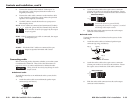
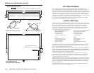
CPU dial switch (RGB 112xi only) — Use a Tweeker or a small
screwdriver to set this switch to the type of
computer attached to the RGB 112xi interface
(IBM, Sun, or SGI), or if the computer produces
sync on green only, set the switch to SOG.
IBM
SGI
SUN
SOG
SOG
DDSP
SERR
SPARE
RGB 109xi and RGB 112xi • Installation
2-5
5
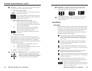
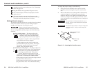
RGB output —Connect coaxial cables to these female BNC
connectors to an RGB ourput device. Connect cables for the
appropriate signal type, as shown below.
6
Audio output connector — One 5-conductor, 3.5-mm captive
screw terminal for audio output. See page 2-13 for audio
connection details.
Installation
Overview
The installation procedure is the same for the RGB 109xi and the
RGB 112xi, except that each interface attaches to a different type
of computer. See “Cabling” on page 2-11 for more information.
To install and set up the RGB 109xi or the RGB 112xi for
operation, perform the following basic steps (the remainder of
this chapter provides detailed steps):
1
Turn off power to the computer or workstation and its
monitor, and unplug the power cable from each of these
devices. Turn off power to the projector, and unplug its
power cord.
2
Disconnect the monitor signal cable from the computer.
If speakers are attached to the computer’s sound card,
disconnect them as well.
3
If desired, change the configuration of jumper J20 (sync
polarity) or J40 (vertical sync width). See “Setting internal
jumpers” on page 2-6.
4
Set the DIP switches ID bit configuration (SOG, DDSP,
SERR). See "Rear panel features" on page 2-3.
5
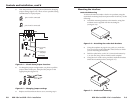
If desired, attach the interface to a table or under a podium
using an optional Extron mounting kit. See “Mounting the
interface” on page 2-9.
6
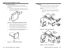
Attach the interface to the computer, attach the local
monitor, if used, to the interface, and attach the projector
to the interface. See “Cabling” on page 2-11.
If you are not using a local monitor with the RGB 112xi,
you must attach an MFTA (multi-frequency termination
adapter) to simulate a monitor.
RGBHV
R
H
G
V
B
S
RGBS
R
H
G
V
B
S
RGsB
R
H
G
V
B
S