


MLC 206 Setup Guide, cont’d
2
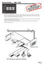
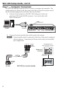
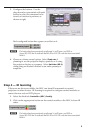
Step 1 — Computer Connection
The MLC 206 must be connected to a PC in order to configure the controller. The
configuration port, shown in the rear panel view below, is used for system control
and for loading configuration and driver files into the MLC.
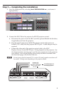
1. Connect a host computer to the MLC 206 Config port via the rear
panel 9‑pin HD female RS‑232 connector. Use a serial cable with
9‑pin D connectors.
A B C D E A B C
IR
Display/Source Control
Extron Switcher Control
Relays IR/RCM
RS-232
D E A B C A BD
1A 1B 2A 2B 3A 3B
1 2 3 4 5 6
Tally Out
MLS
/Power
33-644-01 A
07 01
Config
9-pin
D Connector
Host Desktop
Computer
RS-232
Configuration Port
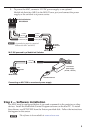
2. Connect all control modules that will be used in the system.
N
Control modules must be connected at this time so they can be configured
with the software. Connections for IR and serial control can be installed
after configuration.
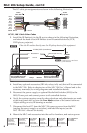
MLC 206
IR
/
RCM
port
MLC IR-IRCM wiring_01-05.eps
A B C D
IR
/
RCM
IRCM control
module(s)
A B C D E
Control
module
connector
CC
+12 VDC
Control signal (IRCM)
Ground ( )
B
B
A
A
MLC 206 to a control module
Total distance from
MLC: 150' (45.7 m) max.
MLC 206
Extron
DISPLAY
POWER
VOLUME
MAX
MIN
VCR DVD Laptop
MLC 206
IRCM-DV+
DVD & VCR CONTROL
PLAY NEXT/FWD PAUSE STOP
TUNER
Tx
PREV/REW
ENTER
TITLE MENU
TV/VCR
DVD VCR