


2
MLC 104 IP Plus Series • Setup Guide (Continued)
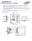
Cabling and Features
Attach cables using the following wiring diagrams as a guide. Full details are available in the MLC 104 IP Plus Series User Guide.
CAUTION: Installation and service must be performed by authorized personnel only.
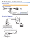
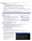
Control — Projector or Display
+V OUT
CM
GROUND
IR OUT
GROUND
SCP
Tx
Rx
DISPLAY
RS-232/IR
A B C D E
COMM LINK
IR IN
LAN
LAN
+
V
OUT
C
M
GROUND
SCP
A B C D E
ABCDE
CO
MM LINK
IR
IN
Transmit (Tx)
Receive (Rx)
Ground ( )
RS-232 IR
Receive (Rx)
Transmit (Tx)
Ground ( )
Bidirectional
Projector or
Display
RS-232 Port
Projector
or Display
IR Receiver
or
(+)
(-)
(+)
(-)
(-)
(+)
Two Single IR Emitters
Ground ( )
IR Output Signal
Unidirectional
IR
Infrared:
• TTL level (0 to 5 V)
• Up to 1 MHz
Select RS-232 protocol via
software or SIS command.
Signals are bidirectional, ±5 V.
RS-232 default protocol:
• 9600 baud
• 8 data bits • 1 stop bit
• no parity • no flow control
NOTE: Each projector or display may
require different wiring. See the
manual that came with the projector
or display, or the Extron device driver
communication sheet for details.
Projector RS-232 / IR Port(s)
Right
Side
Panel
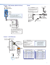
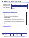
Control — Control Modules,
SCP Control Panels (COMM Link Port)
MLC
Right Side
Panel
123
GROUND
+V OUT
CM
GROUND
IR OUT
GROUND
SCP
Tx
Rx
DISPLAY
RS-232/IR
A B C D E
COMM LINK
DIGITAL
I/O
IR IN
PRESS TA
TWEEKER T
O
LAN
P
RE
SS
T
A
TWEEKER T
O
L
A
N
1
2
3
GROUND
DIGITAL
DIGITAL
I/O
G
R
OU
ND
IR
OUT
T
x
R
x
DISPLAY
DISPLAY
R
S
-232
/
I
R
E
D
C
B
A
SCP communication (IR)
Ground ( )
IRCM, ACM, RCM
+12 VDC
C
B
A
Ground ( )
IRCM/ACM/RCM
+12 VDC
DVD & VCR CONTROL
PLAY NEXT/FWD PAUSE STOP
TUNER
Tx
PREV/REW
ENTER
TITLE MENU
TV/VCR
DVD VCR
IRCM-DV+
SCP 104
DISPLAY
VOLUME
SCP 104
ON
OFF
1
2
3
4
VIDEO
AUX
VIDEO
PC
IMAGE
MUTE
CM/IR/SCP Port
• SCPs: Two maximum per system
• Control modules: four maximum (four module addresses)
• Total distance from port to last device: 200 feet (61 m) maximum
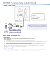
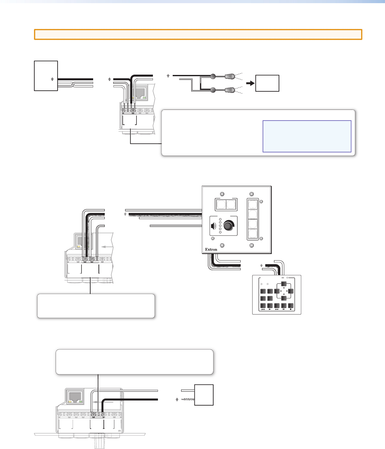
Control — Digital Input or Output (I/O)
RIght Side Panel
123
GROUND
+V OUT
CM
GROUND
IR OUT
GROUND
SCP
GROUND
Tx
Rx
DISPLAY
RS-232/IR
A B C D E
COMM LINK
AB
MLS
RS-232
POWER
12V
DIGITAL
I/O
IR IN
Tx
GROUND
Rx
+12V IN
PRESS TAB WITH
TWEEKER TO REMOVE
LAN
SS
TAB WIT
H
E
R T
O
REM
O
V
E
PR
E
TWEE
K
LAN
G
R
O
UN
D
A B
MLS
MLS
R
S-232
POWER
POWER
12
V
T
x
G
R
OU
N
D
R
x
+
12
V
IN
+
V
OUT
C
M
G
R
OU
N
D
I
R
OUT
G
R
OU
ND
SCP
T
x
R
x
DISPLAY
DISPLAY
RS-232/I
R
A B C D E
ABCDE
C
OMM LINK
IR
IN
Ground ( )
Digital I/O
Switch,
Sensor,
Relay
Digital I/O Ports
These three ports can be used as digital input or output, with or without +5 VDC pull-up.
Once configured, the digital input or output can monitor or trigger events and functions
(toggle relays, issue commands, send e-mail).