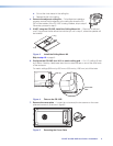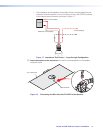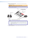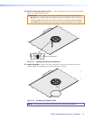
12. Place the CS 120P into the ceiling grid — Place the CS 120P over the tile grid so
that the CS 120P is safely supported on the two short edges. Ensure that the hole in
the tile is aligned with the hole in the CS 120P (see figure 10).
Fig: Mounting the PRE
NOTE:
2' x 2' (600 mm x 600 mm)
grid mounting is the same as 2' x 4'
(600 mm x 1200 mm) grid mounting.
Figure 10. Mounting the CS 120P in a 2" x 2" (600 mm x 600 mm) Ceiling Grid
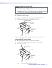
13. Route the speaker wires — Route the speaker wires through the ceiling tile hole.
14. Remove the speaker grille — Carefully remove the grille from the front of the CS 26T.
NOTE: Grille hooks are provided for grille removal, if needed.
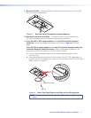
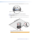
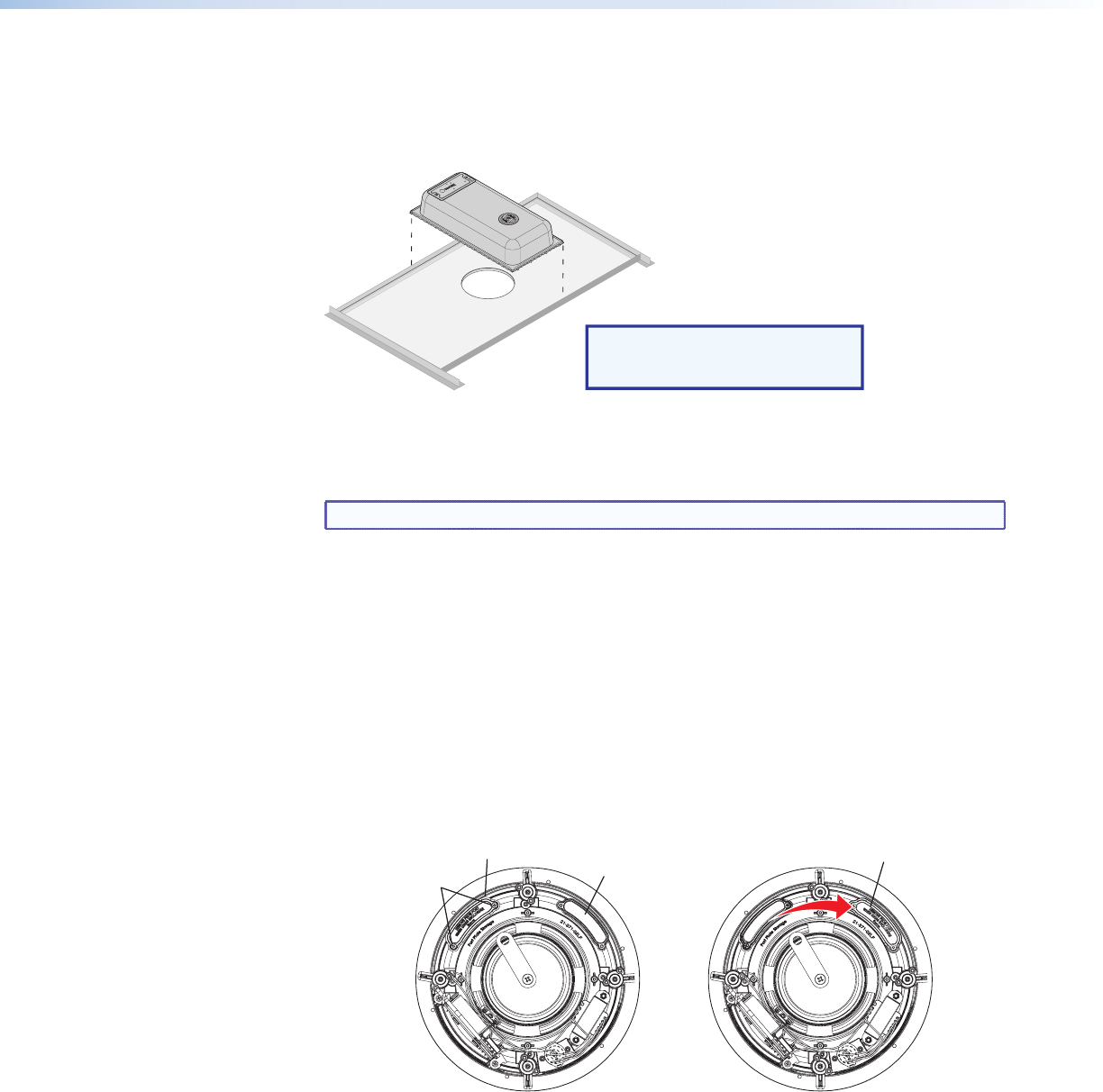
15. Configure the bass reflex port plate. By default, the CS 26T is set up for use with
the CS 120P. If not using the CS 120P, set the plate for an open-back installation.
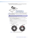
• With the CS 120P (default configuration): Leave the plate in its default location.
The port must be left uncovered (see A in figure 11).
• Open back: The bass reflex port is uncovered by default. In the open back
configuration (without the CS 120P), this port must be closed (covered). If the port
is not covered:
a. Use a Phillips screwdriver to remove the two screws securing the bass reflex
port plate in its storage location.
b. Attach the plate to the bass reflex port using the two screws that you removed
in step a (see B in figure 11).
Bass Reflex Port
(open, uncovered)
AB
Bass Reflex Port
(closed, covered)
Bass Port Plate
(storage location)
Screws (2)
Figure 11. Configuring the Bass Reflex Port Plate
CS 26T and CS 120P User Guide • Installation 8


