ASA Series • Installation and Operation
ASA Series • Installation and Operation
Installation and Operation, cont’d
2-6
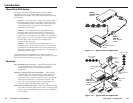
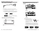
ASA 101 Features and Cabling
2
1
1
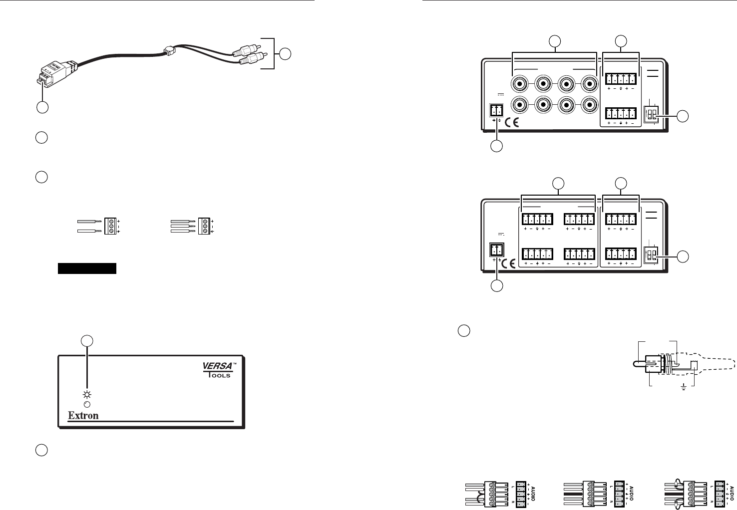
Input plugs — Plug the white RCA connector into the left
output of the stereo source device. Plug the red RCA connector
into the right output of the stereo source device.
2
Output connector — Strip the wires from the mono destination
device, insert them into this 3-pole captive screw connector, and
secure them by turning the screws (see the illustration below).
See Caution
Unbalanced Output Balanced Output
Tip
Ring
Sleeve
Tip
Sleeve
CAUTION
Connect the sleeve to ground (Gnd). Connecting
the sleeve to a negative (-) terminal will damage the
audio output circuits.
ASA 204/ASA 304 Front Panel Features
1
1
Power LED — Lights to indicate that the ASA is on.
ASA 204/ASA 304 Rear Panel Features and
Cabling
POWER
12V
.2A MAX
STEREO INPUTS
MONO OUTPUTS
BAL
UNBAL
ON
SPARE
3
1
4
2
43
21
L
QUAD AUDIO
SUMMING
AMPLIFIERS
R
ASA
204
L
L
R
R
3
4
1
2
ASA 204
STEREO INPUTS
BAL
UNBAL
ON
SPARE
MONO OUTPUTS
3
1
4
2
ASA
304
3
1
4
2
LR
LR
POWER
12V
.2A MAX
QUAD AUDIO
SUMMING
AMPLIFIERS
LR
LR
4
1
2
3
ASA 304
1
ASA 204 input connectors —
Plug up to four stereo audio sources
into these female RCA connectors.
If you do not have pre-terminated
audio cable, wire the male RCA
connectors for unbalanced input as
shown at right.
ASA 304 input connectors — Plug up to four stereo audio
sources into these 5-pole captive screw connectors. Connectors
are included with each ASA, but you must supply the audio
cable. Wire the connectors for the appropriate input type and
impedance level as shown below. High impedance is generally
over 800 ohms.
Unbalanced Input
Tip
Sleeve
Tip
Sleeve
Balanced Input
Tip
Ring
Sleeve (s)
Tip
Ring
Tip
Ring
Sleeve (s)
Tip
Ring
Balanced Input
(high impedance)
(high impedance) (600 ohms)
600 ohms
600 ohms
2-7
Tip (+)
Sleeve ( )


