3G-AE 100 • Panels and Cabling 4
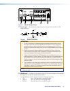
c Loop Through connector — If necessary, plug in an output device to the
Loop Through connector. The SDI input signal is equalized, re-clocked, and routed
to the Loop Through connector. This connector may also be used for cascading to
another 3G-AE 100.
NOTE: It is not required to connect a device to the Loop Through connector in
order to extract audio from the input device.
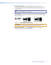
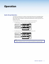
d Analog Outputs — Connect up to four audio output devices to the Analog Outputs,
using a cable with a balanced or unbalanced 3.5 mm, 5-pole captive screw connector.
Wire as shown below.
Do not tin the wires!
Balanced Audio Output
Tip
Ring
Tip
Ring
Sleeves
Unbalanced Audio Output
Tip
No Ground Here
No Ground Here
Tip
Sleeves
LR
LR
Figure 4. Analog Output Connector Wiring
ATTENTION: Connect the sleeve to the ground (Gnd) terminal. Connecting the
sleeve to a negative (-) terminal will damage the audio output circuits.
e Group Select DIP switch — see the Operation section on the next page for
instructions on using the Group Select DIP switch.


