


ceived and optionally de modulated by the repeater as part of
the system protocol when so installed.
Receive-Only Operation
Channels can be programmed to receive-only operation.
Channels cannot be programmed for Transmit-only operation.
Busy Channel Lock Out
With Busy Channel Lock Out programmed, the radio can-
not transmit on a channel already busy. If the channel is busy,
fast pulsing beeps will sound (without stopping), until the PTT
switch is released. The radio must be programmed for, and re-
ceiving, the correct Channel Guard. The combination of Chan-
nel Guard and Busy Channel Lock Out prevents the user from
talking on a channel that is already in use (busy).
When the Busy Channel Lock Out option is enabled with-
out programmed Channel Guard, the user is prevented from
transmitting over a channel until there is no carrier present in
the channel.
Minimum Volume Level
The Front Panel VOLUME controls permit adjustment of
the audio level. Minimum levels are programmable. This fea-
ture prevents missed calls due to a low volume level.
Power Level
Incremental transmitter power level change can be pro-
grammed to permit setting the output power to rated value. The
selected power level will be used for all channels.
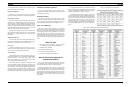
Channel Guard
Channel Guard provides a means of restricting calls to spe-
cific radios through the use of a continuous tone coded squelch
system (CTCSS), or a multi-code digital squelch system
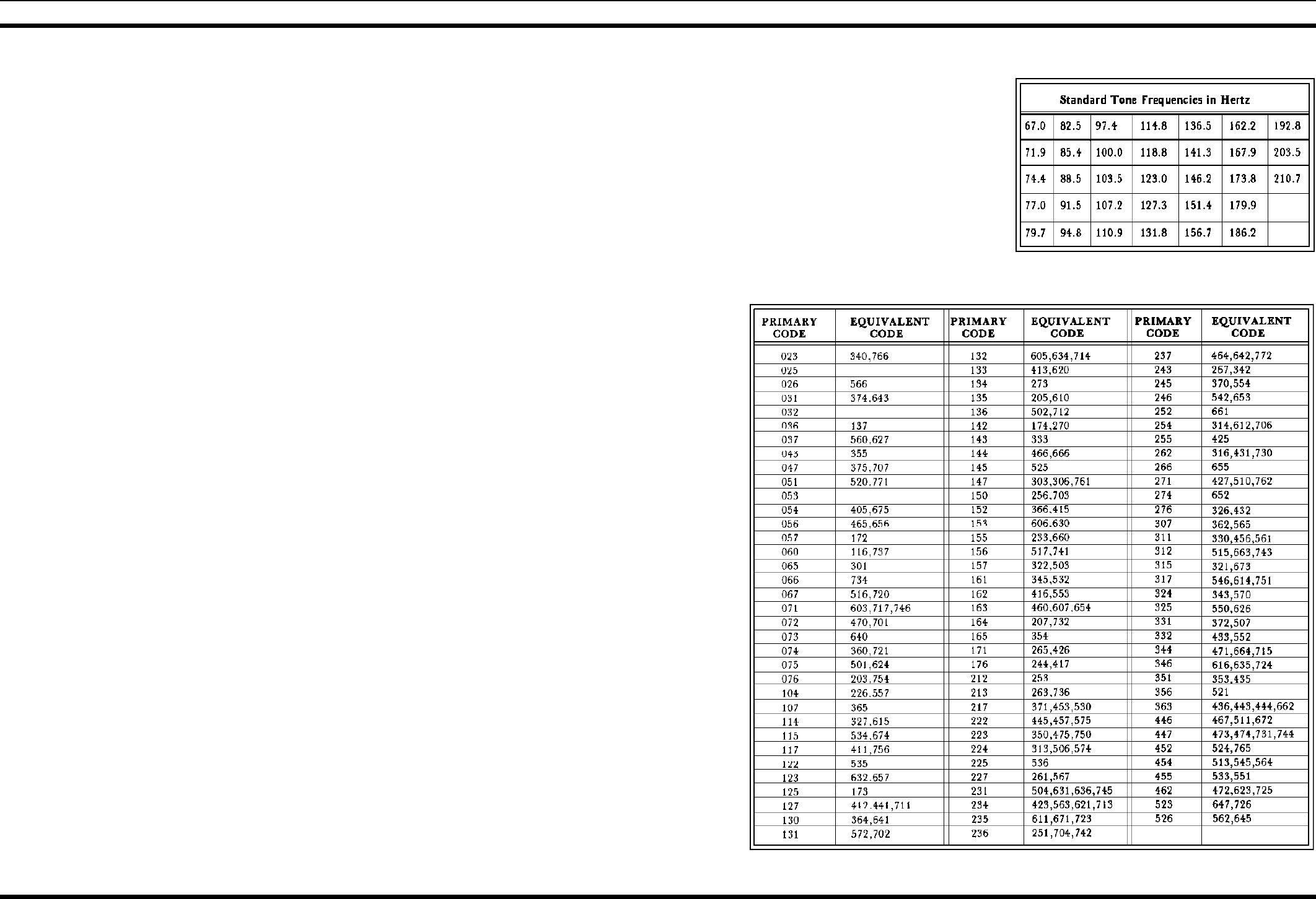
(DCG). Tone frequencies range from 67 Hz to 210.7 Hz. There
are 83 standard programmable digital codes.
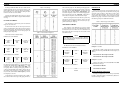
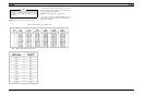
The Channel Guard tone frequencies and codes are soft-
ware programmable. Both tone frequencies and digital codes
may be mixed on each channel. The frequencies and codes are
shown in Tables 1 and 2. A Channel Number display that does
not flash, indicates that Channel Guard is enabled, or that
Channel Guard is not programmed. A flashing Channel Num-
ber indicates that Channel Guard is programmed and disabled.
EXTERNAL SPEAKER (Optional)
The power connector provides a place to connect an exter-
nal speaker. The internal speaker must be disconnected when
an external speaker is used.
BATTERY POWER
The vehicle 12 volt battery with negative ground is all that
is required for operation of the radio. A cable connects the bat-
tery to a male connector mounted on the back of the radio. The
radio can also be powered with the vehicle ignition switch.
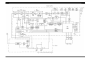
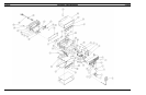
EASY ACCESSIBILITY
The radio circuitry is mostly contained on a single Main
Board, with the exception of the PA Board and the Front Panel
Board. Access to the Main Board and the inside of the radio is
easy with the removal of the top and bottom covers with two
screws each. Then the few adjustment controls (most are ad-
justed with PC programming) can be easily reached. Four more
screws will permit removal of the front panel, giving access to
the Front Panel Board along with the switch and indicator cir-
cuitry.
SERVICE AIDS
• Test Handset Kit (SPK9024), includes Handset
(19A706965P3) and Coiled Cord (19D901619P2)
• Test Adapter Box (TQ0618)
• Programming Cable (TQ3361)
• PC Programming Adapter (TQ3310)
• Power Contact Extraction Tool (458994-2)
DETAILED TYPE 99 OPERATION
AND PROGRAMMING
The original Type 99 programming provides individual,
group and super group call decode. The motorola format two-
tone sequential signaling schemes can also be decoded.
The MDS Conventional radio can be PC programmed with
up to two separate tables of tones. Either the GE Type 99 for-
mat or the Motorola format can be assigned to each tone table.
The tone decoder (Individual, Group and Quick Call for the
Motorola format) can be enabled individually for each channel.
Once enabled, one of the two tone tables can be selected for
each channel.
The Group Call format allows communication with all
radios within a subgroup. The Super Group Call in GE tone
systems) or Quick-Call (in Motorola tone systems) allows
communications between all radios in a system.
The MDS Conventional radio can operate in either the
Type 99 Select Mode or the Type 99 Monitor Mode. In the
Type 99 Select Mode the speaker audio remains muted until
the user’s own Type 99 code is decoded, unmuting the audio
and permitting receipt of the message. At this time an audi-
ble alert sounds and an "A" appears in the display. The "A"
will remain displayed (instead of the selected channel num-
ber) until the RESET button in pressed or the transmitter is
keyed.
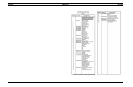
Table 2 - Primary and Equivalent Digital Codes (OCTAL)
Table 1 - Channel Guard Tone Frequencies
LBI-38652 LBI-38652
5