


INTRODUCTION
The Ericsson GE Conventional MDS VHF Radio is a rug-
ged two-way FM mobile radio which operates in the 148-174
MHz frequency band. The MDS is a wide band synthesized ra-
dio utilizing microcomputer technology to provide reliable
high quality simplex two-way mobile communications. Its
transmitter output power level is 40 watts over the wide band-
width of each split. The receiver has an allowable 12 MHz
maximum receive channel separation. There are two versions
available, a 2-channel and an 8-channel. The basic radio pack-
age includes the following features:
• Microprocessor Control
• Synthesized RF Channel selection (frequency control)
• 7-Segment LED Channel Display
• Multi-tone Channel Guard (CTCSS) Encode/Decode
• Multi-code Digital Channel Guard (DCG)
Encode/Decode
• Automatic Hook Switch Channel Guard Disable
• Channel Activity Sensing (CAS)
• Carrier Control Timer (CCT)
• 5 ppm frequency stability
• Type 99 Tone Decode
• Field Programmable with PC
• Fixed Squelch, threshold programmable
• Internal 4-watt Speaker, with volume control
• Front Mounted Microphone Connector
• Rear Mounted Antenna TNC Connector
• Rear entry power connections
• ANI Encode
The small size of the MDS radio makes it ideal for front
mounting in conventional vehicles. The radio is operated with
a simple hand held microphone in combination with the fol-
lowing operating controls, all located on the front panel:
• Power ON/OFF Switch
• Channel UP/DOWN Selector
• Volume UP/DOWN Control
• Monitor Switch for Channel Guard Disable
• Type 99 Tone RESET Switch, to reset the tone decoder.
Refer to the Operator’s Manual LBI-38651 for a complete
description of the operating procedures.
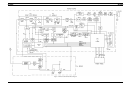
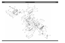
RADIO DESCRIPTION
MAIN BOARD ASSEMBLY
A sturdy aluminum casting houses the Main Board Assem-
bly N29/85154001920. There is complete accessibility to the
Main Board with the radio’s top and bottom covers removed.
The Main Board contains the following circuits:
• Microprocessor and associated Logic
• Frequency Synthesizer
• Transmitter Exciter
• Receiver
• Audio Processing (for both transmit and receive paths)
• Tone and Squelch Processing (for both transmit and
receive paths)
• Voltage Regulators
Logic Circuitry
The radio’s logic circuitry includes the 80C535 microproc-
essor with associated EPROM and Electrically Erasable
PROM (EEPROM) memory and latch circuitry. The Micro-
processor controls the functions of the transmitter, the receiver,
the inputs from the operator and the outputs to the operator.
Synthesizer
A programmable Synthesizer generates both transmit and
receive operating frequencies. It includes a synthesizer chip, a
dual modulas counter, a temperature compensated reference
oscillator (TCXO) and a voltage controlled oscillator (VCO);
all part of an operating phase lock loop, with its requisite loop
filter.
Transmitter
The radio transmitter includes the Synthesizer’s modulated
VCO and the fixed tuned exciter amplifiers. The exciter ampli-
fiers are wideband, covering the VHF band without retuning.
The exciter output is fed to the Power Amplifier Board through
a coax cable. The exciter provides 35 dB of gain to drive the
Power Amplifier with 2 watts. The transmitter output level at
the antenna connector is factory set for a rated output power of
40 watts. The power control circuit detects the power output of
the Power Amplifier. Using the error signal, the power control
circuit varies the DC supply voltage to the first stage of the ex-
citer. This will hold the transmitter output level constant.
SPECIFICATIONS (Cont.)
Spurious Emissions
Radiated Meets FCC requirements
Conducted -57 dBm maximum
Rx Spurious Response 70 dB minimum
Adj Ch(2-Sig) Selectivity -75 dB max @ 30 kHz (EIA)
Intermodulation Attenuation -75 dB minimum
Rx Modulation Acceptance ± 7 kHz minimum
Audio Distortion 2% maximum @ 0.5 Watt (EIA)
10% maximum @ 4 Watts and 1 kHz
Audio Frequency Response Within + 2,-8 of a 6dB/octave de-emphases,
300-3000 Hz (EIA)
Rx Hum and Noise
Unsquelched -50 dB maximum
Squelched -70 dB maximum
Audio Output Power 4 watts, @ <10% Distortion
Speaker Impedance 4 ohms
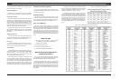
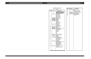
MDS RADIO PACKAGE NUMBERS
PACKAGE NUMBER DESCRIPTION
TLH22 VHF 2 CHANNEL, 40 WATT
TLH28 VHF 8 CHANNEL, 40 WATT
OPTIONS
OPTION NUMBER DESCRIPTION
MC3G DESK TOP MIC
ANIR 1/4 WAVE, ROOF MT ANTENNA W/TNC CONNECTOR
ZM3L EXTERNAL WEATHERPROOF SPEAKER AND CABLE
LS1F MIL SPEC SPEAKER, 4 OHMS, 5 x 5
CD1E SPEAKER CABLE
PD1A NOISE FILTER KIT
SU1C ALARM RELAY KIT
EC1A DOC POWER SET
MA1L DESK TOP RADIO MOUNTING WEDGE
PS1D 240 VAC-12 VDC, 13A 50/60 Hz Power Supply
PS5K 120 VAC-12 VDC, 13A 50/60 Hz Power Supply
LBI-38652 LBI-38652
2