


17
TAPE
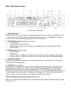
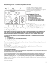
This ‘loop’ connects an external recording device to the USP-1 preamplifier via RCA outputs and inputs.
While this traditionally has been a cassette player or DAT player, this connection could also be a hard
drive based recording device as long as the input and output connections are analog RCA audio
connections.
To enable the tape monitor loop you must connect to the inputs AND outputs on the USP-1 labeled
"TAPE" on the rear panel. To engage the tape monitor loop, select TAPE from the USP-1 front panel or
remote.
Please note -these outputs are unaffected by any external signal processing.
To engage the recording device, first press TAPE from the front panel or remote and then it will allow you
to “monitor” the audio that the recording device will record. When you are ready to record, engage the
recording device.
HT INPUT
Connects to an external multi-channel, or ‘home theater’ processor using standard RCA type analog
connectors. Connect left, right, and subwoofer (if your front speakers are not full range) analog outputs
on the processor to the USP-1 HT inputs. When the HT BYPASS button is selected, all USP-1 functions
are disabled, and it becomes a pass-through for the connected external processor. The HT inputs are
only active when the USP-1 is on.
Connecting To Amplifiers and Speakers
When connecting to amplifiers and speakers, make sure to use the properly labeled left
channel, right channel and subwoofer connections.
Check to make sure that you have connected the proper cables in the proper sequence:
1) Left and right channel USP-1 outputs (either full range or High Pass) into left and right
channel amplifier inputs. 2) Left and right channel amplifier outputs to left and right speakers.
3) USP-1 subwoofer outputs for powered subwoofer inputs.
NOTE: Do not connect speakers directly to the USP-1.
Also use high quality, 100% shielded, oxygen free copper cables.
Trigger Connections
12VDC trigger used to remotely trigger a connected device on and off. Please ensure that the total of the
loads connected to this trigger do not exceed 500mA.