


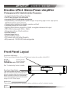
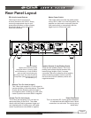
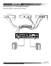
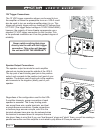
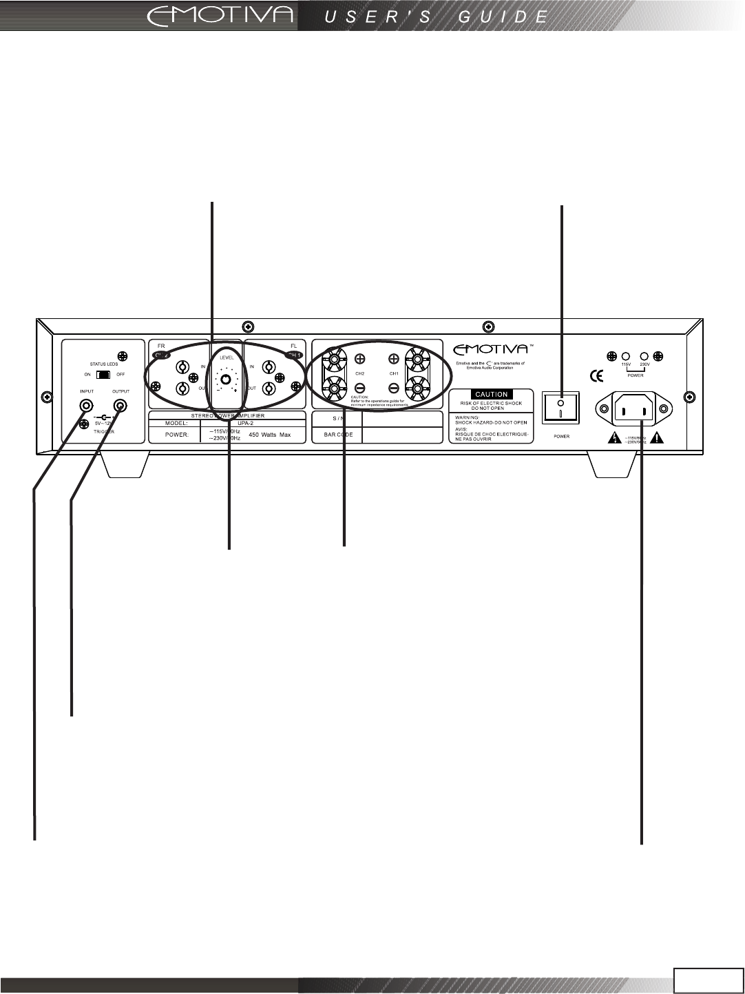
Rear Panel Layout
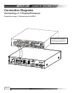
RCA Audio Inputs/Outputs
These inputs are for signal input
for each channel on the UPA-2. Simply
connect the appropriate input to your
preamplifier/processor or other preamp
level audio device. Loop outputs and
Master Power Switch
This rocker switch provides the master power
for the UPA-2. After it is in the ON position, the
amplifier can be turned on manually from the
front panel switch or automatically with the
trigger input via 3.5mm input jack.
Remote Turn On Jack (input)
This 3.5mm jack accepts a 5-12 volt input for
remote activation of the UPA-2. This mates
directly with the Emotiva processor trigger out
and supplied cable. If building your own cable,
center is positive and outer shield is negative.
This 3.5mm jack accepts a +12 volt output for
remote activation of the other device. This mates
directly with the Emotiva products trigger in
and supplied cable. If building your own cable,
center is positive and outer shield is negative.
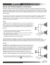
Speaker Outputs (5 way Binding Posts)
These are the speaker outputs. The 5 way
binding posts accept stripped speaker wire,
banana plugs (single or dual), or spade
connectors. Be sure to observe correct polarity
when connecting speakers and be sure that
the wires do not touch between positive and
negative terminals.
Power Receptacle
This is a standard IEC 2 prong power receptacle.
It is advised that this amplifier have a direct
connection to a wall outlet. Do not plug into a
“power strip”.
Page 9
Remote Turn On Jack (output)
.
Level Control
When set to Minimum,the
amplifier has no output;when
set to Maximum, it has 32dB of
gain and will match the gain
structure of all the other Emotive
Amplifiers.(Note:Loop out is not
controlled by it.)
inputs are paralleled.