


Page 12
Page 13
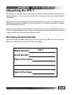
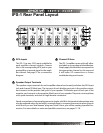
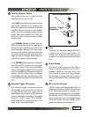
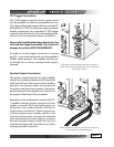
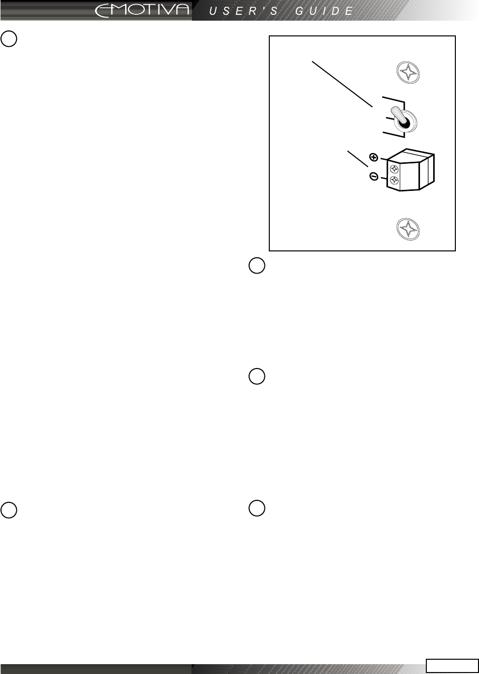
Turn On Selector Switch
This switch allows you to select how the
amplier will turn on and o.
In the ON (Up) position, the switch on the
front of the amplier is the method you
will use to power up and power down the
amplier. Please note that in this congu-
ration, you must manually power up and
power down the amplier each time you
use it or it will have unnecessary standby
current draw.
In the SIGNAL (Middle) position, the am-
plier automatically turns on whenever it
senses an audio signal on any one of the
seven amplier channels. The circuit stays
active for a 30 minutes after the absence of
any audio signal to account for quiet pas-
sages of music or dialogue and muting the
audio (for a phone call for example).
In the TRIGGER (Down) position, the ampli-
er’s ON and OFF functions are controlled
by a trigger from a source or preamplier
device. The trigger accepts 12 VDC and will
turn the amplier on whenever a trigger is
present (See #5). When there is no trigger,
the amplier goes into standby mode. This
is the preferred method for activating the
IPS-1.
External Trigger Connection
This external trigger connection allows
the amplier to be turned ON and OFF by
a control device such as a source unit or
preamplier. It can also be used with most
home automation controllers. The trigger
requires a 12 VDC trigger. This is the pre-
ferred method of activating the IPS-1. See
page 16 for connection details.
Fuse
This fuse is for the power supply of the IPS-
1 chassis. It is a TL15AL type rated a 15A
Slo-Blo, 250 V. If the fuse ever fails, be sure
to replace it with the same type and rated
fuse.
Power Switch
This switch should remain in the ON po-
sition for normal operation of the IPS-1
amplier. When you are away from your
entertainment system for long periods,
this provides a convenient way to switch
the unit o without having to unplug power
cords.
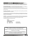
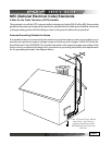
IEC Line Cord Socket
The IPS-1 comes with a detachable line cord
which connects here. Plug the line cord into
an AC wall socket which is correctly con-
gured with the voltage and current supply
specied for the IPS-1. Do not plug this line
cord into a power strip, it must plug directly
into a wall socket. For more details on AC
power considerations, see page 13.
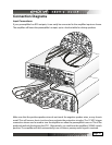
Turn On Selector Switch
External Trigger
Connection
5
6
7
4
8