


Reference Manual
00809-0100-4690, Rev EA
March 2007
3-7
Rosemount 2088 and 2090
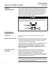
Access Requirements When choosing a mounting location and position, take into account the need
for access to the transmitter.
Make wiring terminations through the conduit openings at the top of the
electronics housing. The field terminal side of the transmitter is clearly marked
on the transmitter neck. Test terminals are incorporated on the terminal block;
you do not need access to the electronics compartment to perform calibration
procedures.
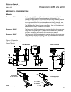
The transmitter electronics compartment contains the electronics module with
failure mode and security jumpers, and the optional LCD meter. Consider the
need for access to both compartments when installing the transmitter. Refer
to Figure 3-5 for transmitter dimensional drawings.
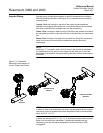
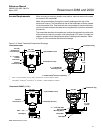
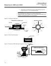
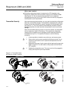
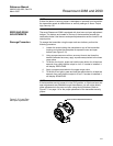
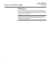
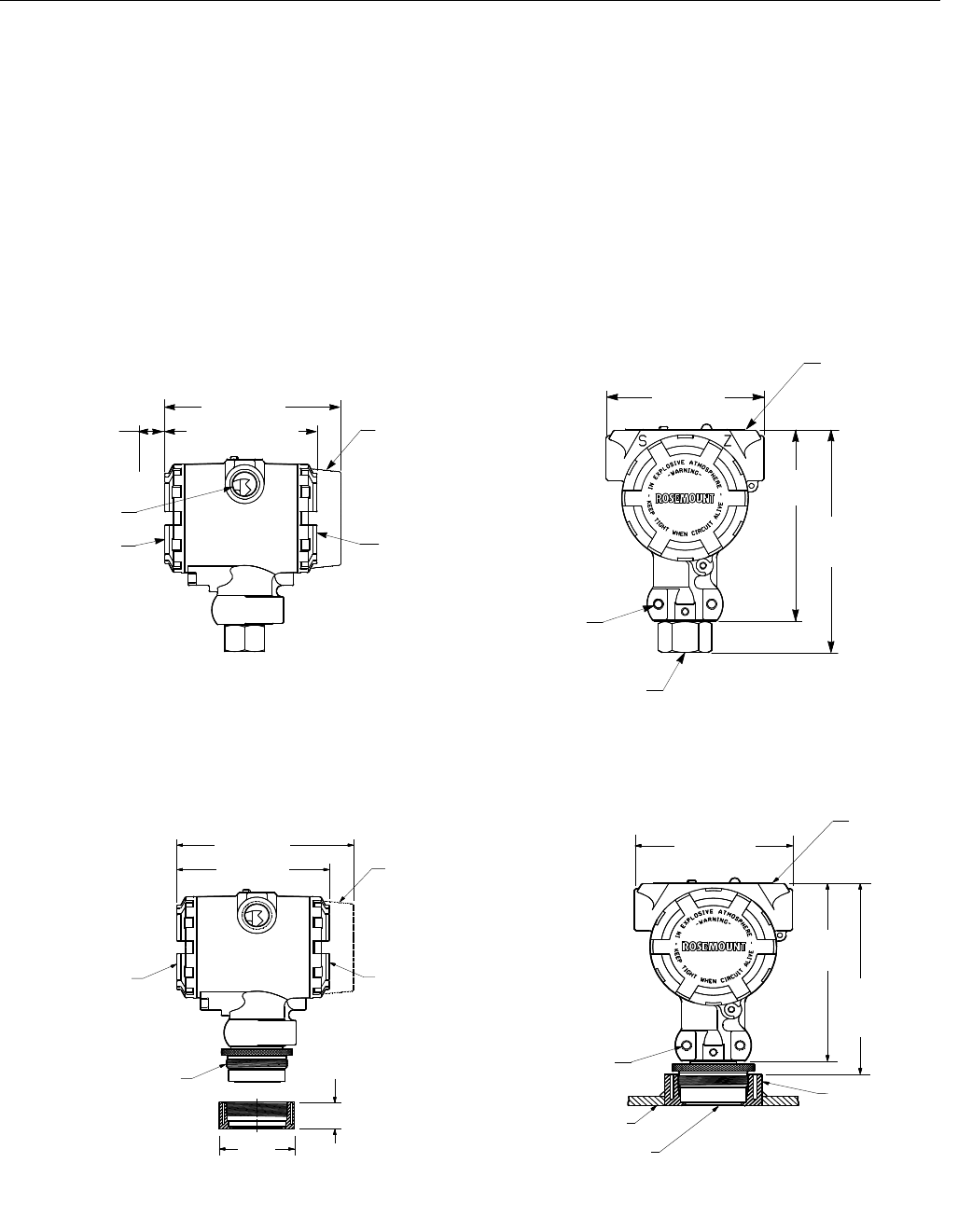
Figure 3-4. Smart Transmitter Dimensional Drawings.
* M20 ϫ 1.5 Female (CM20), PG 13.5, and G
1
/2 Female (PF
1
/2) also available as options.
†
DIN 16288 G
1
/2 Male, RC
1
/2 Female (PT
1
/2), and M20 ϫ 1.5 Male (CM20) also available.
2 ϫ ½–14 NPT*
Conduit
Connection
Terminal
Connections
5.0 (125)
Optional Meter Cover
Transmitter Circuitry
Certifications Tag
2 ϫ¼–20 UNC-2B
Mounting Holes
½–14 NPT
Female
†
Process Connection
4.3 (110) Max.
3.9 (100)
0.75 (20)
Clearance for
Cover Removal
4.7
(120)
5.75
(146)
Rosemount 2088
2.38
(60)
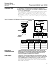
5.0 (125)
Optional Meter Cover
Transmitter Circuitry
Terminal
Connections
M44 ϫ 1.25
Weld Spud
2 ϫ
1
/4–20 UNC–2BX
Depth 0.60
Mounting Holes
4.7
(120)
3.9 (100)
0.82
(21)
Weld Spud
Certification Tag
4.3 (110)
Rosemount 2090P (1.5-in.)
Vessel Wall
NOTE: Dimensions are in. (mm).
5.1(130)
Typical