


Reference Manual
00809-0100-4690, Rev EA
March 2007
3-13
Rosemount 2088 and 2090
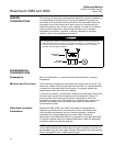
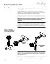
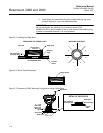
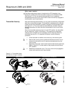
Figure 3-10. Rosemount 2088
Smart Signal Wiring Terminals.
FAILURE MODE AND
SECURITY JUMPERS
Failure Mode
As part of normal operation, the Rosemount 2088/2090 Smart Pressure
Transmitter continuously monitors its own operation. This automatic
diagnostic routine is a timed series of checks repeated continuously. If the
diagnostic routine detects a failure in the transmitter, the transmitter drives its
output either below or above specific values depending on the position of the
failure mode jumper or switch.
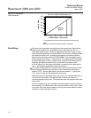
The values to which 4–20 mA transmitters drive their output in failure mode
depend on whether they are factory-configured to standard or
NAMUR-compliant operation. The values for each are as follows:
Standard Operation
Linear output: 3.9 ≤ I ≤ 20.8 mA
Fail low: I ≤ 3.75 mA
Fail high: I ≥ 21.75 mA
NAMUR-Compliant Operation (Option Code C4)
Linear output: 3.8 ≤ I ≤ 20.8 mA
Fail low: I ≤ 3.6 mA
Fail high: 21.0 ≤ I ≤ 23.0 mA
To determine the failure mode configuration of your transmitter, review the
failure mode options using a 275 HART Communicator.
NOTE
The failure mode configuration, whether standard or NAMUR-compliant, is
configured at the factory and can not be changed in the field.
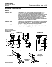
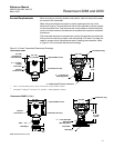
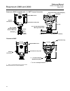
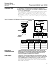
Jumper Locations Without a meter installed
The failure mode alarm jumper is located on the front side of the electronics
module just inside the electronics housing cover and is labeled ALARM (See
Figure 3-11). Do not remove the transmitter cover in explosive atmospheres
when the circuit is alive. Both covers must be fully engaged to meet
explosion-proof requirements.
Positive
Negative
Test