


Micro Motion
®
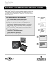
Series 3000 Transmitters and Discrete Controllers 5
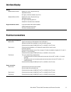
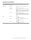
Interface/display
Electrical connections
Display
Models 3300 and 3500 Backlit LCD, 128 × 128 pixel, bit map
Adjustable contrast
Non-glare, chemical-resistant acrylic lens
Models 3350 and 3700 Backlit LCD, 128 × 128 pixel, bit map
Adjustable contrast
Non-glare tempered glass lens
Suitable for hazardous area installation
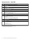
Keypad membrane switch Large push buttons with tactile feedback
Software-defined function keys
Chemical-resistant polyester
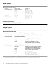
Input and output connections
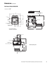
Rack-mount Type D connectors per DIN standard 41612 (IEC 603-2)
Available as solder tails (standard) or screw terminals (optional)
Screw terminals accept 24 AWG (0.25 mm
2
) to 16 AWG (1.5 mm
2
) wires
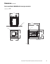
Panel-mount Screw terminals (standard) or I/O cable with remote DIN rail-mount screw
terminals (optional)
Remote terminals attach to any of four rail types. I/O cable is available in lengths of 2, 5, and 10
feet (0.6, 1.5, and 3 meters)
Screw terminals accept 24 AWG (0.25 mm
2
) to 16 AWG (1.5 mm
2
) wires
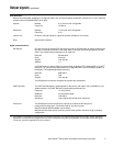
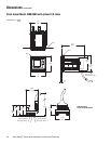
Field-mount Two color-coded wiring compartments:
• Compartment with intrinsically safe terminals has two 3/4-inch NPT or M20 × 1.5 conduit
openings
• Compartment with non-intrinsically safe terminals has three 3/4-inch NPT or M20 × 1.5
conduit openings
Screw terminals accept 22 AWG (0.34 mm
2
) to 16 AWG (1.5 mm
2
) wires
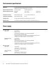
Power connection
Rack-mount Screw terminals are fixed to rack chassis
Ground makes first and breaks last
Screw terminals accept 18 AWG (0.75 mm
2
) to 14 AWG (2.5 mm
2
) wires
Panel-mount Screw terminals accept 18 AWG (0.75 mm
2
) to 14 AWG (2.5 mm
2
) wires
Field-mount Screw terminals accept 18 AWG (0.75 mm
2
) to 12 AWG (4.0 mm
2
) wires