


9
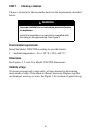
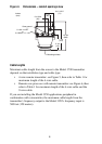
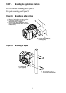
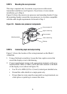
STEP 5. Mounting the core processor
This step is required only for remote core processor with remote
transmitter installations (see Figure 6). If you have a 4-wire remote
installation, go to Step 6.
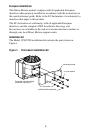
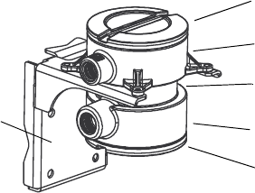
Figure 10 shows the remote core processor and mounting bracket. Using
the mounting bracket, mount the core processor in a location compatible
with the cable length requirements discussed in Step 1.
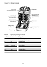
Figure 10. Remote core processor components
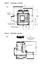
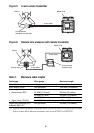
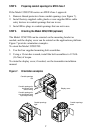
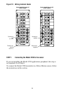
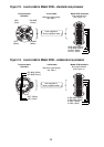
STEP 6. Connecting input and output wiring
Figure 11 shows the location of the wiring terminals on the Model
3350/3700.
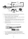
1. Using a flat-head screwdriver, loosen the four captive screws that
secure the display cover to the housing.
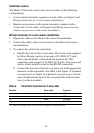
2. Connect input/output wiring to the appropriate terminals on the gray
terminal block. Refer to Table 2 and to the label attached to the back
of the display cover (shown in Figure 12).
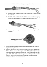
• Use 22 to 16 AWG (0,35 to 1,5 mm
2
) twisted-pair shielded wire.
• Ground the cable shields at a single point only.
• If more than two wires must be connected to a single terminal, use
a butt splice or spade lug to connect the wires.
Core processor
Lower conduit ring
End-cap
Mounting bracket
Core processor lid
Upper conduit ring