


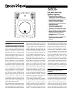

Sx500+ 400-Watt Two-Way Speaker System
Sx500+ 400-Watt Two-Way Speaker System
3
capacity of 400-watts long term (1,600- watts
peak) per ANSI/EIA RS-426-A 1980. The fol-
lowing guidelines will help relate this to an ap-
propriate power amplifier output rating.
1. To use the Sx500+ to full capacity, skilled
experts in sound-system installation and
operation will obtain the best results if
the power amplifier is 2.0 to 4.0 times
the long-term average noise- power rat-
ing of the speaker system. For the
Sx500+, this is 800 to 1,600 watts.
The caution cannot be made strongly
enough, however, that this arrangement
is only for experts or those who can disci-
pline themselves against “pushing” the
system for ever-higher sound levels and
who can avoid “accidents” such as cata-
strophic feedback or dropped micro-
phones.
2. A more conservative, “normal” amplifier
size, which will produce audible results
nearly equal to those of the “expert” rec-
ommendation, is 1.0 to 1.4 times the long-
term average noise-power rating of the
speaker. For the Sx500+, this is 400 to
640 watts.
3. To be very conservative, one can use an
amplifier rated at 0.5 to 0.7 times the
long-term average noise-power rating of
the speaker. For the Sx500+, this is 200
to 280 watts.
Request P.A. Bible Addition No. Two
(“Power Handling Capacity”) for more back-
ground on these recommendations.
Service
In the unlikely event the Sx500+ requires ser-
vice, the woofer can be removed from the
front. The high-frequency driver can be re-
moved from the rear by first removing the
input panel. A service data sheet is available
from Electro-Voice.
Stand Mounting
When used on a stand, the stand must be
placed on a stable surface. The stand must
be rated to support systems of 38.6 kg
(85 lb) or greater. It must have a base diam-
eter of 1.22 m (4 ft) or greater. The bottom of
the speaker should be no higher than 1.52 m
(5 ft) from the bottom of the stand. The user
must be sure that safe use on a stand is not
affected by wind or any other conditions.
The Sx500+ can be mounted on the 100BK
speaker stand or any other stand with a
1
3
/
8-
inch diameter shaft.
Suspending Sx500+ Enclosures
WARNING: Suspending any object is
potentially dangerous and should be
attempted only by individuals who have a
thorough knowledge of the techniques and
regulations of rigging objects overhead.
Electro-Voice strongly recommends that
the Sx500+ be suspended taking into
account all current national, federal, state
and local regulations. It is the responsi-
bility of the installer to ensure the Sx500+
is safely installed in accordance with all
such regulations. If the Sx500+ is
suspended, Electro-Voice strongly
recommends that the system be inspected
at least once a year. If any sign of weakness
or damage is detected, remedial action
should be taken immediately.
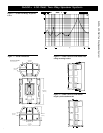
The Sx500+ enclosure contains eight
M8 x 1.25 inserts (see Figure 7) which are
built into the enclosure for the purpose of
suspension. Before the enclosure is sus-
pended, these inserts are used to attach plates
that hold the two halves of the enclosure to-
gether in addition to providing a way to sus-
pend the enclosure.
The suspension kits that are available for the
Sx500+ are listed below. Please refer to in-
dividual suspension-kit engineering data
sheets for full details and safety information.
The first approach is to suspend individual
Sx500+ enclosures. The Mb700 forged eye-
bolt attachment kit (see Figure 9) is an eye-
bolt suspension kit. It includes a top and bot-
tom mounting plate to secure the two halves
of the enclosure, in addition to the necessary
hardware. Typically it will be necessary to
attach two cables to the top eyebolts and to
“pull-up” on the bottom plate. The Mb500
wall/ceiling mounting bracket (see Figure 8)
encompasses the top and bottom of the en-
closure with a bracket attached to the two
plates to secure the halves of the enclosure.
Additionally, it has features to make suspend-
ing the Sx500+ easier and more flexible.
Electro-Voice recommends the use of the
Mb500 in all but the simplest situations. The
Mb500 has supplementary holes to allow the
Sx500+ to be attached to a wall or ceiling
and aimed at an audience.
The second approach is to suspend multiple
Sx500+ enclosures. The Sx500+ enclosure
is not designed to suspend multiple enclo-
sures from itself. If an “array” is required,
then multiple Mb500’s must be used. Arrays
may be constructed vertically by “daisy
chaining” two Mb500’s from each other. The
Mb600 horizontal array kit allows the easy
and secure construction of horizontal arrays,
using Mb500’s to support the enclosure.
Architects’ and Engineers’
Specifications
The loudspeaker shall be a compact vented-
box type. The low frequencies shall be re-
produced with one horn-loaded DL15SX
381-mm (15-in.) woofer. The high frequen-
cies shall be reproduced by a DH2T, high-
frequency compression driver with a pure-
titanium diaphragm, coupled to a
75° x 60° constant-directivity horn molded
into the front baffle of the enclosure. The
system will use a passive crossover-equal-
izer network with protection for the high-
frequency driver. The loudspeaker shall meet
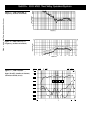
the following performance criteria: fre-
quency response of 60-16,000 Hz, –3 dB;
power handling of 400-watts long term and
1,600-watts short term, with a shaped ran-
dom-noise input per ANSI/EIA RS-426-A
1980; sensitivity of 100-dB SPL at 1 meter
with a 1-watt, 300-2,000-Hz pink-noise in-
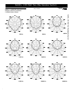
put; 6-dB-down horizontal coverage angle
of 75° + 14°/– 20° in the 2,000- to 20,000-
Hz range; 6-dB-down vertical coverage
angle of 60° + 11°/– 8° in the 2,000- to
20,000-Hz range; crossover frequency of
1,600 Hz; nominal impedance of 8 ohms and
minimum impedance of 5.2 ohms in full-
range mode. Paralleled input and output con-
nectors shall be present, consisting of Neu-
trik Speakon
®
NL4MP connectors. The en-
closure shall be constructed of polypropylene
structural foam and fitted with a powder-
coated steel grille, three integral handles, a
stand socket for mounting on
1
3
/
8
-inch stands, rubber feet and mating
sockets to facilitate stacking. Dimensions
shall be 838 mm (33 in.) high x 673 mm