


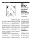

Sx500+ 400-Watt Two-Way Speaker System
Sx500+ 400-Watt Two-Way Speaker System
2
the woofer grille.
Speaker Protection
The Sx500+ like all other vented systems ex-
periences rapidly increasing cone excursion
below the box-tuning frequency, while the
acoustic output decreases rapidly. To ensure
a long woofer life even when used at high
power levels, it is recommended that some
form of electronics be used to control un-
necessary woofer cone excursion.
Graphic equalizers and active crossovers are
two methods that can be used to prevent low-
frequency signal below band-pass from go-
ing to the loudspeaker. When using an ac-
tive crossover, a high-pass filter with a cut-
off frequency of 32- to 45-Hz will provide
the necessary protection. The filter should
have a slope of at least 12 dB per octave.
Such subpass band filters are found in many
crossovers and equalizers manufactured by
Electro-Voice, as well as other commercially
available equipment.
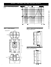
Enclosure Construction
The Sx500+ enclosure is contructed of very
durable structural foam that is hard to dent,
scratch or break. The structural foam enclo-
sure allows for the high- and low-frequency
horns, the stand mount and the suspension
points to be molded into the enclosure. It also
allows for three handles to be integrated into
the enclosure.
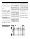
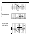
Frequency Response
The combination of a 15-inch woofer, wide-
bandwidth high-frequency driver and an
equalized crossover results in the wide and
smooth overall response shown in Figure 1.
This response was measured at 3.05 meters
(10 feet), using a 4-volt swept sine-wave in-
put in an anechoic chamber using the inter-
nal passive crossover. No external equaliza-
tion was used. Figure 1 has been averaged
and corrected for 1 watt at 1 meter.
Connections and Biamping
The Sx500+ is equipped with two parallel
Neutrik Speakon
®
NL4MP connectors. In the
full-range mode, as supplied by the factory,
pins 1+ and 1– are the inputs to the system.
Another system can be connected in parallel
by using the other connector. Care must be
taken not to abuse the amplifier by connect-
ing impedances which are too low.
The user may put the system in biamp mode
by removing the input panel and moving a
connector from the full-range mode to biamp
mode, as noted on the crossover. In biamp
mode, 1+, 1– are the LF inputs and 2+, 2–
are the HF inputs.
Constant-Directivity Speaker System
The crossover frequency and speaker- com-
ponent geometries have been selected so that
the directional characteristics of the woofer
and constant-directivity high-frequency horn
match at the crossover frequency to create a
special system type — the constant-direc-
tivity system. At higher frequencies, the hori-
zontal coverage pattern remains constant and
the vertical pattern smoothly transitions to a
60° angle above 5,000 Hz. Response within
the 75° x 60° rated coverage angle is uni-
form, which means dependable audience
coverage without “hot spots” or dead zones
at certain frequencies. The 75° x 60° disper-
sion characteristic also helps avoid early re-
flections from nearby floor or side-wall sur-
faces which could degrade performance. The
controlled directivity of the high- and low-
frequency transducers also eliminates re-
sponse irregularities caused by diffraction off
nearby enclosure edges and, in combination
with an essentially flat on-axis frequency
response, produces a total acoustic power
output that is uniform with frequency.
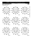
Directivity
A unique feature of the Sx500+ is the con-
stant-directivity dispersion provided by the
75° x 60° horn. The polar response of the
system at selected one-third-octave band-
widths is shown in Figure 2. These polar re-
sponses were measured in an anechoic envi-
ronment at 6.1 meters (20 feet) using one-
third-octave pink-noise inputs. The frequen-
cies selected are fully representative of the
polar response of the system. Beamwidth of
the system utilizing the complete one-third-
octave polar data is shown in Figure 3. Di-
rectivity factor, R
,
and directivity index, D
i
,
are plotted in Figure 4.
Power-Handling Capacity
The Sx500+ is shipped in full-range mode
using an internal crossover. In biamp mode,
the long-term average power-handling ca-
pacity is as follows:
Low Frequency: 400 watts
High Frequency: 60 watts
Electro-Voice components and systems are
manufactured to exacting standards, ensur-
ing they will hold up, not only through the
most rigorous of power tests, but also
through continued use in arduous, real-life
conditions. The EIA Loudspeaker Power
Rating Full Range (ANSI/EIA RS-426-A
1980) uses a noise spectrum which mimics
typical music and tests the thermal and me-
chanical capabilities of the components.
Electro-Voice will support relevant addi-
tional standards as and when they become
available. Extreme, in-house power tests,
which push the performance boundaries of
the woofers, are also performed and passed
to ensure years of trouble-free service.
Specifically, the Sx500+ passes ANSI/EIA
RS-426-A 1980 with the following values:
R = 5.76 ohms (1.15 x (R
E
+ 1.86))
R
E
= woofer DCR
1.86 =horn-load impedance correction
P
E(MAX)
= 400 watts
Test voltage = 48.00 volts rms,
96.00 volts peak (+6 dB)
The “peak” power-handling capacity of a
woofer is determined by the peak test-volt-
age amount. For the Sx500+, a 96.00-volt
peak test-voltage translates into 1,600-watts
short-term peak power-handling capacity.
This is the equivalent of four times the “av-
erage” power-handling capacity, and is a
peak that can be sustained for only a few mil-
liseconds. However, this sort of short dura-
tion peak is very typical in speech and mu-
sic. Provided the amplifier can reproduce the
signal accurately without clipping, the
woofer will also perform accurately and
reliably, even at these levels.
Amplifier Power Recommendations
As noted in the Power-Handling Capacity sec-
tion above, the Sx500+ has a random-noise power