Electro-Voice EVF/EVH User Manual 41
6.0 Rigging-Strength Ratings and Safety Factors (cont’)
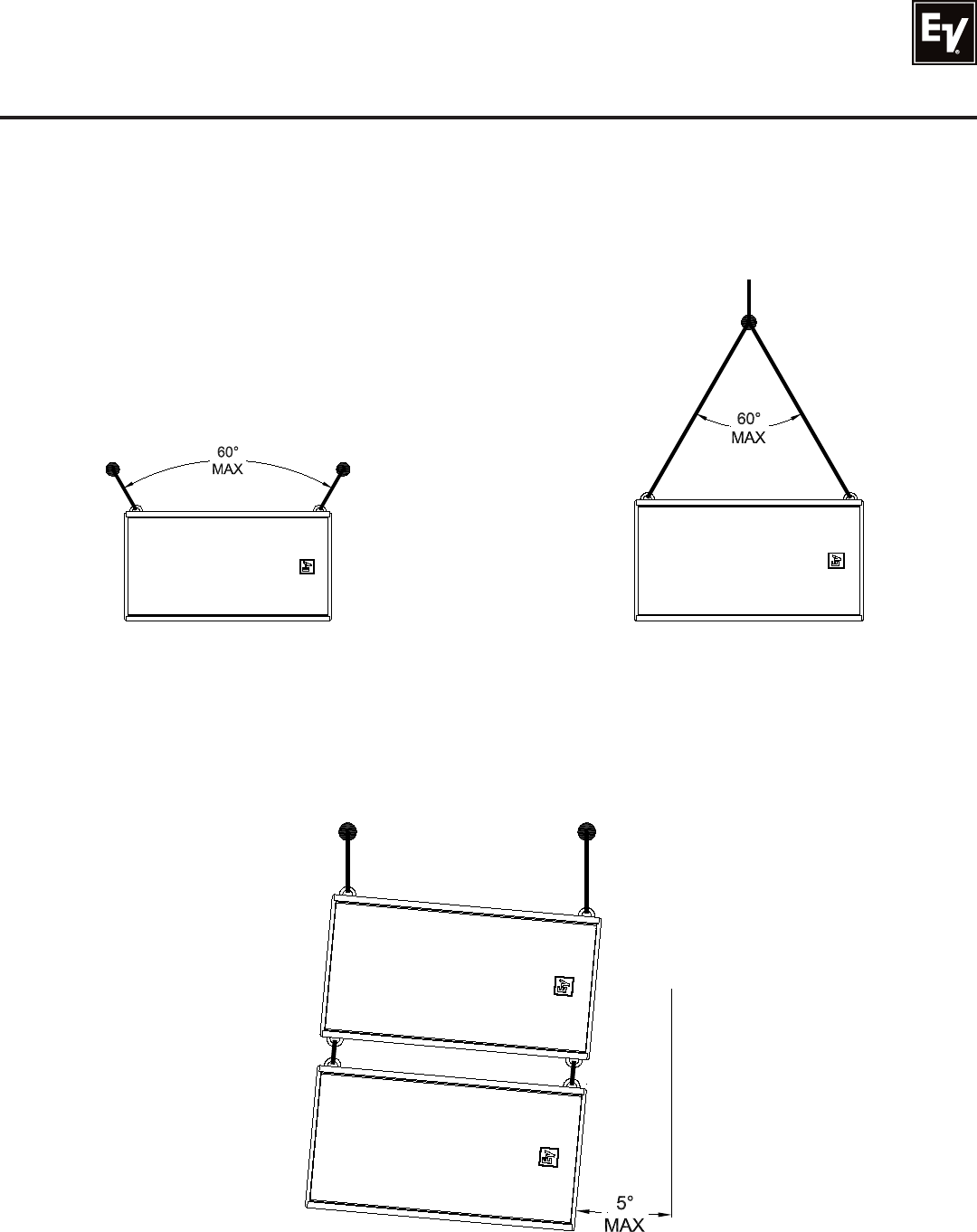
6.32 Suspension-Line Angles
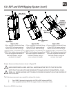
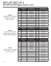
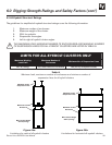
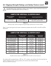
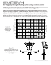
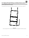
Refer to Table 9 and Figure 25 for specific eyebolt angle and weight limitiations when using all-eyebolt
clusters. These limits are not to be exceeded under any circumstances. If a higher safety factor than 8:1
is required, the angle limitations for each eyebolt may actually decrease to a number less than what is
shown in Figure 25.
Always make sure that the suspension line is in the plane
of the eyebolt, as shown in Figure 17. Readjust the eyebolt
during the installation if necessary to maintain this alignment.
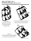
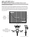
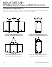
Figure 27:
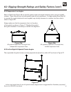
Left-to-right angle limits for an all-eyebolt cluster (angle shown exaggerated for illustration purposes)
6.33 Left-to-Right All-Eyebolt Cluster Angles
The suspended all-eyebolt cluster must be perpendicular (plumb) to within ±5° as shown in Figure 27.
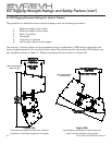
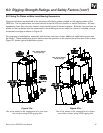
Figure 26a:
All-eyebolt suspension-line angle limit,
independent suspension lines
Figure 26b:
All-eyebolt suspension-line angle limit,
bridled suspension lines


