CONTRACTOR PRECISION SERIES
8 Owner‘s Manual
2.2 Operating Voltage
The power amplifier receives its power supply via the MAINS IN connector. Only the provided power cord may be used.
During installation, always separate the power amplifier from the mains. Connect the power amplifier only to a mains network,
which corresponds to the requirements indicated on the type plate.
Mains Operation & Resulting Temperature
The power drawn from the mains network is converted into output power to feed the connected loudspeaker systems and into
heat. The difference between power consumption and dispensed power is called power dissipation (P
d
). The amount of heat
resulting from power dissipation might remain inside of a rack-shelf and needs to be diverted using appropriate measures.
The tables on page 31 allow the determination of power supply and cabling requirements. The tables are meant as auxiliary
means for calculating temperatures inside of a rack-shelf system/cabinet and the ventilation efforts necessary.
The column P
d
lists the leakage power in relation to different operational states. The column BTU/hr lists the dispensed heat
amount per hour. Power consumption is direct proportional for other mains voltages. The following conversion factors are
meant for easy conversion: 100V = 2.3; 120V = 1.9; 240V = 0.96
2.3 Mains Switch
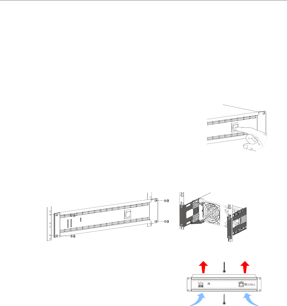
The Mains Switch on the front panel separates the power amp from the mains. Turning the
Mains Switch to ON starts booting up the power amp. A soft start circuit compensates
mains inrush current peaks and thus prevents triggering AC mains fuse when switching on
the amplifier. Speaker system switch-on is delayed by approximately 2 seconds via output
relays, effectively suppressing any possible power-on noise, which otherwise might be
heard through the loudspeakers. PROTECT-LED light and fans are at high speed during
this delay. This indicates all protections are working fine.
2.4 Mounting
CPS amplifiers have been designed for installation in a conventional 19-inch rack case. Attach the power amp with its frontal
rack mount ears using 4 screws and washers as shown in following illustration.
Additionally securing the amplifier at the rear becomes necessary, if the rack case in which the power amplifier has been
installed will be transported. Failure to do so may result in damage to the power amplifier as well as to the rack case. Attach
the power amp as shown in the illustration using 4 case nuts and screws. Brackets for securing the power amplifier are
available as accessories.
2.5 Ventilation
As with all Electro-Voice power amps with fan cooling, the airflow direction is front-
to-rear, obviously because there is more cold air outside of the rack case than
inside. The power amplifier remains cooler and dissipating the developing waste
heat in a specific direction gets easier. In general, setting up or mounting the
power amplifier has to be done in a way that fresh air can enter unhindered at the
front and exhausted air can exit at the rear. When installing the power amp in a
case or rack system, attention should be paid to these details to provide sufficient
ventilation. Allow for an air duct of at least 60 mm x 330 mm between the rear
panel of the power amplifier and the inner wall of the cabinet/rack case. Make
sure that the duct reaches up to the cabinet’s or the rack case’s top ventilation
louvers. Leave room of at least 100 mm above the cabinet/rack case for ventilation. Since temperatures inside of the cabinet/
rack case can easily rise up to 40 °C during operation of the power amp, it is mandatory to bear in mind the maximum
allowable ambient temperature for all other appliances installed in the same cabinet/rack case.


