


Converting Coverage Specs to A Layout
How do you convert polar coverage to listening-plane coverage as you design sound systems?
There are two ways. One is to use the EV ceiling speaker layout program that does the
conversion for you. For more elaborate analysis you can use EASE. Ease can determine
intelligibility and map the SPL output of your entire installation. Usually that's not necessary
however, as you can easily do a little bit of math and figure out what the real listening plane
coverage angle of the speaker is.
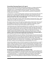
The second way to compute the listening-plane coverage is to start with the exact polar plot of the
speaker and use a conversion table. (Real polar plots directly from test equipment are more
accurate than an artists' redrawing.) Polar plots are usually normalized to the on-axis value,
which is usually labeled “0 dB.” For every angle off-axis, there is a “difference-figure” between this
normalized on-axis value and the volume at that angle.
To convert to listening-plane coverage, add the 3dB Correction Factor figure from Table 1 for that
angle off-axis to the figure from the polar plot. If you're doing this correctly, the coverage pattern
is getting more narrow than the original polar plot.
By using the actual polar plot of the speaker and applying these correction factors from the chart,
the angle that results in a figure of -6 dB is the angle of coverage for the speaker. This angle is
the real 6dB-down angle for that loudspeaker when it is projected onto the listening plane.
Remember that this coverage angle is valid regardless of the ceiling height.
If we take the polar plot of a hypothetical speaker with 140° coverage, we see that at 70° off-axis
(140° total for both sides) the level is down 6 dB compared to the on-axis level. By looking at the
polar-to-listening-plane conversion chart, we need to add -9.3 dB to this -6dB figure to find the
actual level on the listening plane at this off-axis angle. We find that the level of this 140° speaker
(as specified by the polar coverage) is actually -15.3 dB, not -6 dB, down at 70° off-axis.
Therefore, listeners located at this off-axis angle will hear sound that is more than 15 dB down
from the level they hear when they pass directly underneath the speaker. This is a very large
difference. Keep in mind that these coverage angles are averaged over the frequency spectrum
and will generally not give the rated coverage at every specific frequency.
To find the actual 6dB down point of the speaker for the listening plane, take the actual polar plot
of the speaker and at every increment of 5° off-axis, apply the correction factors from the polar-to-
listening-plane conversion chart. The 6dB-down angle is that angle at which the new figure reads
-6dB (polar dB down plus the additional dB down from the correction factor). While the final
resulting angle depends on the actual polar plot of the speaker, it can generally be said that most
speakers with a nominal polar coverage of 140° can be expected to reach -6dB between 45° and
55° off-axis, resulting in an actual listening-plane coverage between 90° and 110°.
Now let's take a speaker that has a 180° polar coverage. Let's further assume that it is a mythical
“perfect” speaker where the volume doesn't go down at all at any angle. Its polar pattern when
placed in a ceiling is a perfect half-circle. To find the real 6dB-down point, we apply the correction
factors and find that at 60° off axis (120° coverage), the sound is 6 dB down. Therefore, the real
listening-plane coverage of a perfect 180° speaker is only 120°. Now, let's realize that a speaker
with a 180° polar coverage “spec” can actually be down 6 dB at full off-axis and still have a spec
of 180°. In this case, its coverage is going to be even less than 120°.
An Example of Coverage Pattern vs. Speaker Size
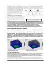
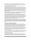
For installations involving basic low level background music and paging, system designers often
specify 8-inch cone loudspeakers for distributed overhead systems, at least in part because they
represent the traditional choice. In many cases, however, you can achieve equal or better results
— at a significant savings — by using specially designed 4-inch elements. Characterized by
somewhat smoother frequency response and less susceptibility to feedback than 8-inch
elements, 4-inch units are also generally less expensive and offer a real advantage in reduced
directivity.
ElectroVoice/Dynacord BGM Guide Page 19