


20
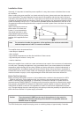
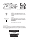
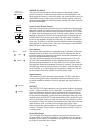
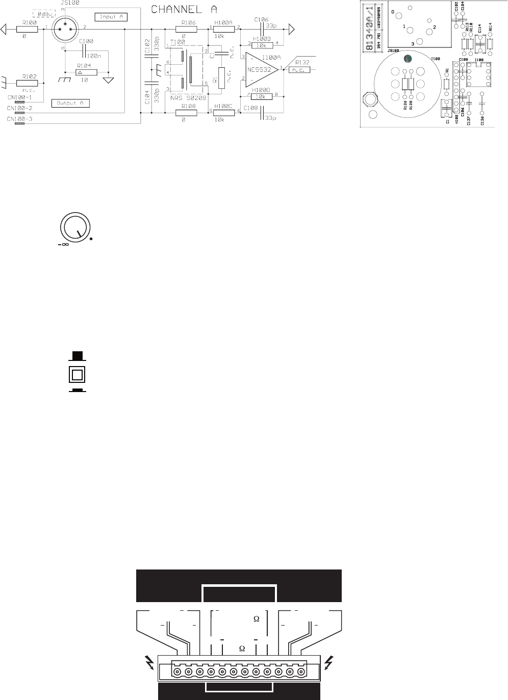
gure: block diagram input channel A gure: printed board assembly area
channel A – transformer retrotting
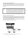
Level Control
dB-scaled rotary controls for adjusting the power amplier’s overall
amplication. This control should be positioned between the 0 dB and
the -6 dB marks to prevent distortion in source devices. The labeling
indicates the actual attenuation applied to the internal specied factor
of amplication.
Input Routing
If the switch is set to parallel/mono, the input connectors CHANNEL
A and CHANNEL B are electrically linked for direct parallel operation.
With only a single audio signal source connected, both channels are
driven, while their volume levels are still individually controlled via the
level controls A and B.
If the switch is set to its dual/stereo position, channels A and B are se-
parately amplied (two channel or stereo mode).
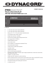
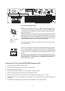
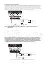
Power Outputs A&B
The loudspeaker cables are connected to the power amplier through high-performance binding posts
– with the necessary screw-plugs being supplied. For connection purposes, it is possible to remove the 12-
pole terminal plug. Cables with a maximum diameter of 2.5 mm2 can be utilized. To provide exible connec-
tions, all oating output voltages – 25 V, 70 V, and 100 V (ISOLATED OUTPUTS) – as well as the low-impe-
dance output (DIRECT OUTPUTS) of both channels are directly accessible.
LEVEL
0 dB
-9
-1
6
-3
0
-1
-4
-2
-3
-5
-6
-1
2
DUAL/STEREO
PARALLEL/MONO
INPUT ROUTING
70
100
0
100
700
+
+
25V
100V
+
70V
+
+
ISOLATED OUTPUTS
DIRECT OUTPUTS
BRIDGED
1200W/8
600W
+
LOW IMPEDANCE
AUDIO TRANSFORMER OUTPUTS
100V
+
25V
+
70V
+
B A
4
DUAL
B
A
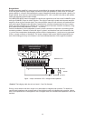
gure: power outputs of the DPA 4260