


17
DESCRIPTION
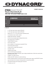
Especially designed for permanent installations, the DPA-Series power ampliers offer performance-consistent
and reliable operation of PA-systems with 2 individual loudspeaker lines, each. Therefore, DPA-Series power
ampliers are most suitable for company intercom, alarm and background music transmission installations in
ofces and commercial areas, congregation and sport centers, schools, houses of worship, hotels, hospitals,
shopping malls and super markets, cruise ships, and other similar applications.
Each power amplier incorporates two high-performance output transformers. Next to 100 V, 70 V, and 25 V
oating outputs, the direct outputs provide the possibility to also drive loudspeaker systems with low-impe-
dance down to a minimum of 4 ohms. Simultaneous operation of low-impedance speaker systems and oating
loudspeaker lines on a single output channel of the power ampliers is possible as well.
The integrated 45 Hz LO-cut lter with 18 dB/oct. slope protects the connected loudspeaker lines from unwan-
ted ultra-low frequencies.
Comparator circuitry constantly monitors the input and output signals of the power ampliers and activates
their internal limiters whenever non-linear operation is encountered which reliably protects the connected
loudspeaker systems against overload conditions and clipping, saturation of the power supply transformers,
and overvoltage at the outputs. The DPA-Series power ampliers’ transmission and sound qualities are ab-
solutely superb. The employed comprehensive dimensioned power supply units with low-interference toroidal
transformers ensure that the stated nominal performance specications are accomplished, even in most de-
manding and critical installations. Since the DPA-Series power ampliers do not employ V/I-Foldback-Limiter
circuits, operation on complex loads up to ±90° phase angles is possible without a problem.
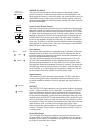
Quick optical information on the power ampliers’ momentary operational status is provided through easily
readable LED indicators, individually showing whether a channel is ready for operation, a signal is present at
the output, if any of the limiter circuits and/or one of the protection circuits has been activated.
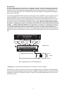
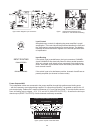
The inputs are electronically balanced and carried out as XLRF-type and as binding post clamping connectors
as well. Parallel linking the two connector types at the input provides the possibility to utilize the carried-th-
rough signals to feed additional power ampliers, without the necessity for special split-cables. Both inputs
can be optionally retrotted with input transformers. Through Input Routing switches it is possible to congure
the DPA-Series power ampliers for stereo, parallel-monaural, or bridged-mode operation.
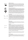
The dB-scaled level controls – extremely precise and good to operate potentiometers – are located on the
rear of the appliances. A Ground-Lift switch which helps eliminating ground noise loops by separating the
amplier circuit ground from the common ground of the enclosure is also to be found on the rear panels. Con-
veniently connecting the loudspeaker lines to the power ampliers is provided through a binding post strip,
where all voltages – 25 V, 70 V, 100 V – and the low-impedance output are present on individual screw-clamp
connectors. The rear panel service mains switches allow turning the power ampliers’ power on directly. Using
the provided power remote input, remote-start is also possible.
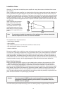
Consistent thermal stability of the power ampliers is obtained through extremely silent running fans which are
automatically switched stepwise depending on the ampliers’ operation mode. The front-to-rear air circulation
guarantees trouble-free operation in rack-shelf enclosures of any size.
Several other features of the DPA-Series power ampliers are revealed within this owner’s manual. Therefore,
please take the time to carefully and entirely read the provided information.
CONTENTS
Description ........................................................................................... 17
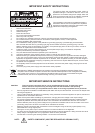
Installation Notes ................................................................................. 18
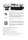
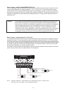
Rear View ............................................................................................ 19
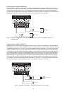
Inputs ................................................................................................... 19
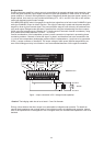
Outputs ................................................................................................ 20
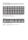
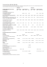
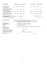
Specications ...................................................................................... 27
Block Diagram ..................................................................................... 43
Dimensions .......................................................................................... 44