


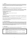

6.5 Level meter and CLIP indicator
The green LED-indicators -13dB and 0dB (1) together with the red CLIP-LED (2) allow to monitor the output level,
effectively avoiding overdrive conditions that lead to distortion and overload at the power outputs which could
damage the connected loudspeaker systems.
- If the red CLIP-LED (2) shortly lights during program peaks, maximum non-distorted modulation is achieved.
- Continuous lighting or blinking of the red CLIP-LED (2) signals overdrive. In this case the input level has to be
reduced.
- If the green LED indicator (1) does not light or is only briefly lit with the red CLIP-LED blinking at the same time,
this signals the encountering of an overload or short-circuit condition at the output. In this case the impedance of
the connected load has to be checked.
Caution During normal operation the red CLIP-LED should only light briefly and shortly!
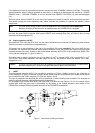
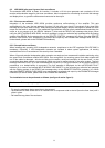
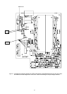
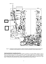
7. Switching the output voltage (only to be performed by a qualified service technician!)
The DPA 4120 and DPA 4140 amplifiers allow the connection of 50V, 70V, 100V or low-impedance loudspeaker
systems (4 ohms). They are factory-preset to an output voltage of 100 V. Switching the output voltage to 4 ohms,
50V or 70V can be performed by changing the bridge B411 on the power amplifier printed board assembly 84187
(DPA 4120) or 84175 (DPA 4140):
Caution Before opening the appliance, make sure to disconnect the mains and/or battery power source!
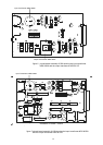
- To open the appliance, the top panel has to be removed.
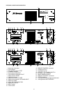
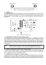
- The bridge B411 (yellow wire) has to be removed from the contact B407 and re-attached to the desired contact
(see table 1) (see also figure 8 respectively figure 9).
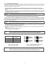
- he coding-bridges S405 and S406 for the output recognition have to be inserted according to the illustration in
figure 5.
(the inserted coding-bridge is marked in black)
- The top panel has to be re-attached.
Note By using a waterproof marker pen and after switching the output voltage, the newly set value
has to be marked in the filed "OUTPUT VOLTAGE" on the rear panel of the appliance.
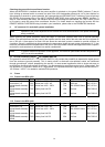
output bridge
B411 to
100 V B407
70 V B408
50 V B409
4 ohms B410
table 1 bridge B411 settings figure 5 coding-bridges S405 / S406 settings
switching the output voltage output recognition OUTPUT CONFIG
Caution It is possible that during operation shock-hazard output voltages can be present at the POWER
OUTPUT connector (>34V peak value). Thus, the connected loudspeakers have to be installed in
accordance to applicable security standards and regulations (see also paragraph 8.5.2).
31