


26
Contents
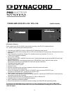
Performance Features .................................................................................................................................23
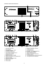
Indicators, controls and connections ...........................................................................................................25
1. Utilization ..................................................................................................................................................... 27
2. Installation ...................................................................................................................................................27
3. Before the first operation..............................................................................................................................27
3.1 Mains operation ................................................................................................................................... 27
3.2 Battery operation 24V DC.....................................................................................................................28
4. INPUT ..........................................................................................................................................................28
5. Outputs.........................................................................................................................................................29
5.1 POWER OUTPUT................................................................................................................................. 29
5.2 POWER OUTPUT for 100V (70V or 50V) loudspeaker systems ......................................................... 29
5.3 SINGLE CALL and obligatory reception relays OVERRIDE BYPASS................................................. 29
5.4 POWER OUTPUT for low impedance loudspeaker systems............................................................... 29
5.5 MONITOR output.................................................................................................................................. 30
5.6 REMOTE CONTROL connector (only NRS 90225)............................................................................. 30
6. Indicators ..................................................................................................................................................... 30
6.1 STANDBY indicator ..............................................................................................................................30
6.2 READY indicator...................................................................................................................................30
6.3 PROTECT indicator .............................................................................................................................. 30
6.4 GROUND FAULT indicator...................................................................................................................30
6.5 Aussteuerungskontrolle und CLIP-Anzeige..........................................................................................31
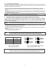
7. Switching the output voltage........................................................................................................................ 31
8. Enhanced application field........................................................................................................................... 32
8.1 General input module NRS 90225........................................................................................................32
8.2 Remote module NRS 90222.................................................................................................................32
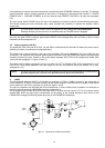
8.3 NRS 90208 input transformer for the floating, balanced input .............................................................33
8.4 NRS 90227 output transformer for the floating, balanced monitor output............................................33
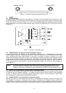
8.5 NRS 90224 pilot tone and ground fault surveillance ............................................................................ 35
8.5.1 Pilot tone surveillance ................................................................................................................. 35
8.5.2 Ground fault surveillance ............................................................................................................35
9. 19"-case and 19“-rack shelf system installation ..........................................................................................38
10. Ground lift switch CIRCUIT ATO CHASSIS SWITCH................................................................................. 38
11. Fuses ...........................................................................................................................................................38
11.1 Fuses in the DPA................................................................................................................................ 38
11.2 Fuses in the DPA................................................................................................................................ 38
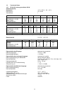
12. Power amplifier specifications .....................................................................................................................42
12.1 DPA 4120 power amplifier 200 W.......................................................................................................42
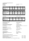
12.2 DPA 4140 power amplifier 400 W.......................................................................................................43
13. Extension specifications............................................................................................................................... 44
13.1 NRS 90225 general input module.......................................................................................................44
13.2 NRS 90222 remote module ................................................................................................................44
13.3 NRS 90208 input transformer for floating, balanced input ................................................................. 44
13.4 NRS 90227 output transformer for floating, balanced monitor output................................................44
13.5 NRS 90224 pilot tone and ground fault surveillance ..........................................................................44
14. Block diagrams ............................................................................................................................................ 67
14.1 Power amplifiers DPA 4120 / DPA 4140 .............................................................................................67
14.2 NRS 90225 general input module.......................................................................................................68
14.3 NRS 90222 remote module ................................................................................................................69
14.4 NRS 90224 pilot tone and ground fault surveillance ..........................................................................70
15. Warranty.......................................................................................................................................................72