9
© 2006 Directed Electronics—all rights reserved
4-CHANNEL XA-6004
LR
INPUT
RR
0.5
4
1.4
LEVELHI PASS LOWPASS
REAR
0.5
4
1.4
FRONT
HI PASSLOW PASSLEVEL
HI-INPUT
X-OVER
X-OVER
HPFLPF
FULL
HPFLPF
FULL
500Hz50Hz
500Hz50Hz
500Hz50Hz
500Hz50Hz
0.25V
5V
0.25V
5V
90
90 90 90
8dB
0dB
8dB
0dB
BASSBASS
LF
RF
INPUT
PRT
PWR
12
8 9 10 11
43567
FRONT REAR
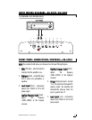
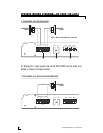
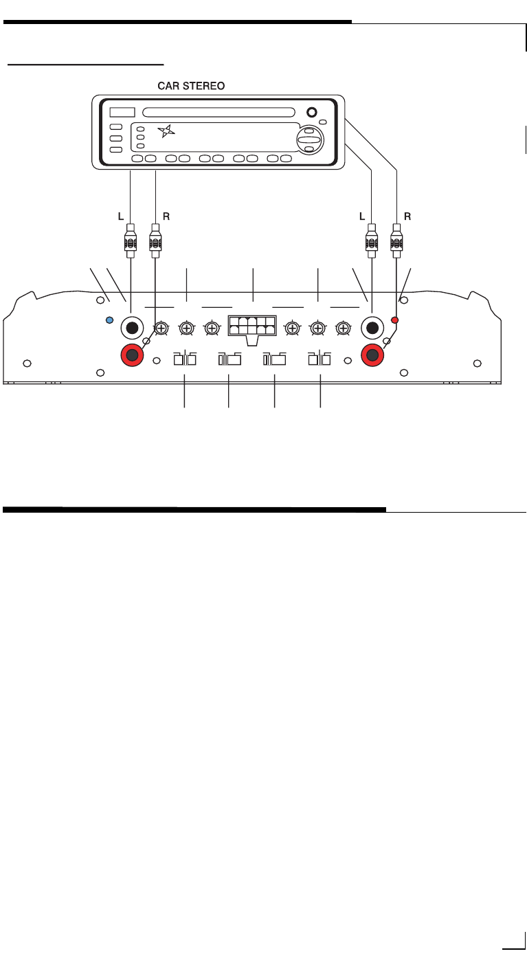
INPUT WIRING DIAGRAM—XA-6004
NNOOTTEE::
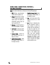
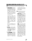
The numbers listed below are referenced on the Input Wiring Diagram.
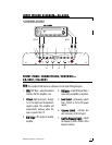
FRONT PANEL CONNECTIONS/CONTROLS—
XA-5001/XA-8001
1.
PPWWRR
(LED blue) - when illuminated
indicates that the amplifier is on.
2.
HHII IInnppuutt
(high level input) - Accepts
1v to 10v input from the headunit’s
speaker output. The amplifier will
automatically wake-up when the
input is greater than 1V.
3.
RRCCAA OOuuttppuutt
- RCA output to another
amplifier.
4.
RRCCAA IInnppuuttss
- accepts RCA input from a
source unit, preamplifier, or equalizer.
5.
LLeevveell CCoonnttrrooll
- continuously adjusts
from 150mV to 5V for full power
output.
6.
CCrroossssoovveerr SSwwiittcchh
- activates low
pass crossover, or full (all pass).
7.
LLooww--PPaassss FFrreeq
quueennccyy CCoonnttrrooll
- adjusts
the frequency (30Hz–250Hz) of the
lowpass crossover


