


15
© 2006 Directed Electronics, all rights reserved
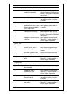
● RTA (real time analyzer)
● Soldering iron and solder
● Utility knife
● Wire brush or sandpaper for chassis grounding
● Wire crimper
● Wire cutters
● Wire strippers
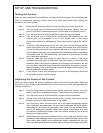
Step By Step Installation
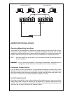
Step 1 Determine the location for the amplifier. Refer to the Choosing Mounting
Locations section of this guide for detailed information.
Step 2 Decide on the system configuration for your amplifier. For system sugges-
tions, refer to the Speaker Connections section of this guide.
Step 3 Run all the wires from the amplifier location to the speakers, source unit, and
battery. Do not connect the battery at this time. Be sure to run RCAs and
power and speaker wires away from factory electrical wires and system as
they pose a great potential for induced system noise.
Step 4 Pre-drill amplifier mounting holes. Be sure to "think before you drill". Gas
tanks, fuel lines, and other obstructions have a nasty way of hiding them-
selves. For best results use a marking pen to mark the mounting holes and
pre-drill these holes with a standard 1/8" drill bit.
Step 5 Mount the amplifier. Make sure the amplifier is mounted on a flat surface. If
this is not possible, do not over tighten the screws so that the chassis of the
amplifier is twisted or bent.
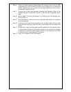
Step 6 Turn the vehicle's key switch to the off position.
Step 7 Disconnect the vehicle's battery ground terminal.
Step 8 Connect power wires to the amplifier (ground first, then 12 V(+) and REM).
Step 9 Connect the RCA and speaker wires to the amplifier. Check the quality of
your speakers and signal connections. This will determine the ultimate per-
formance of your Orion amplifier. Refer to the Signal Input and Output Level
Controls and Speaker Connections sections of this guide for correct wiring
instructions.
Connect the ESP
®
-2 cable that came with the amplifier from the amplifier’s
ESP port to the security system’s ESP port.
Step 10 Reconnect the ground terminal to the battery after power, speaker, and RCA
connections are completed.
Step 11 Set crossovers. Refer to the Internal Crossover Configuration section of this
manual for detailed instructions.
Step 12 Once satisfied that all connections and settings are correct, install the fuse
located near the vehicle's battery and proceed to the Testing the System sec-
tion of this manual.
WARNING! Never exceed the recommended fuse size of this amplifier. Failure to do so will
result in the voiding of your warranty and possible damage to the amplifier.