1111
© 2005 Directed Electronics, Inc. all rights reserved
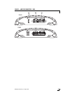
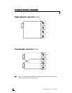
Refer to figure 5 for wiring details.
1.
IInnppuutt SSiiggnnaall
- Connect these RCA
jacks as described in the
Front Panel
Connection
section of this guide.
2.
SSllaavvee//MMaasstteerr SSwwiittcchh
Set the slave/master switch
on the master amplifier to the
MASTER position.
Set the slave/master switch
on the slave amplifier to the SLAVE
position.
Setting the slave/master
switch on both amplifiers will auto-
matically set the I/O RCA jack
configuration according to each
amplifier’s slave or master designa-
tion.
NNOOTTEE::
One master amplifier can control up to three slave
amplifiers in this combination. Multiple identical
master/slave combinations can be added to any
given system.
3.
PPhhaassee SSwwiittcchh --
Set the phase
switches of all synced amps to the
same position (all at 0° or all at
180°).
4. In order to achieve safe, optimal perfor-
mance, the LPF, Bass EQ, and Subsonic
Filter controls on all synced amps must
be set to the same position.
5.
SSiiggnnaall CCoonnnneeccttiioonn
- Connect an RCA
cable between the OUT RCA jack of
the master amplifier and the SLAVE
IN RCA jack of the slave amplifier as
shown in the Figure 5.
6.
SSuubbwwooooffeerr SSppeeaakkeerr CCoonnnneeccttiioonn
- In
this amplifier combination each
amplifiers must drive its own sepa-
rate subwoofer(s). Connect the
speaker terminals of each amplifier
to any combination of one or more
subwoofers that results in nominal
impedance between one and four
ohms (D600—2 to 4 ohms).
Make sure that each amplifier sees
the same speaker impedance.
WWAARRNNIINNGG::
The amplifier’s gain control is bypassed completely
in SLAVE mode. Do
NNOOTT
move the MASTER/SLAVE
switch to SLAVE position when the amplifier is
connected and playing. Do
NNOOTT
connect any signal
source to the amplifier in SLAVE mode that
exceeds 200mV.
PARALLEL SYNCED GAIN CONNECTIONS/SETTINGS


