


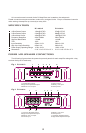
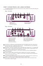
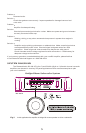
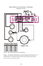
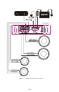


INPUT CONNECTIONS AND AUDIO CONTROL
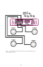
The following figures show the input/audio control end panels for each amplifier along with
a key to show the layout.
1.RCA lnput jacks
2.Gain Control
3.Bass Boost Control
4.Crossover Frequency
5.X-Over Mode Switch
6.RCA Output Jacks
7.Power lndicator
Fig.3 D3 400.2
1
2
3
4
5
6
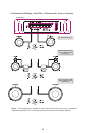
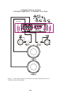
Fig.4 D3 400.4
1
2
3
4
5
6
7 8 9 10
1.Front RCA lnput jacks
2.Rear RCA lnput jacks
3.Front Gain Control
4.Rear Gain Control
5.Bass Boost Control
6.Channel lnput Selector
7.Front X-Over Frequncy Selection
8.Front X-Over Mode Switch
9.Rear X-Over Frequncy Selection
10.Rear X-Over Mode Switch
11.Power lndicator
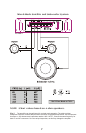
Gain Control Allows the nominal operating level of the amplifier to be set in conjunction
with the level of input voltage from the source unit. The D3 amplifiers will accommodate
low level (RCA) input ranging from 500 mV~5 V.
Bass Boost Acts like an equalizer with an adjustable gain fixed at 45 Hz. This adjustment
gives you up to 18 dB of boost at that frequency. This can be used to compensate for lack
of low-frequency response in the car audio environment.
Crossover Frequency Selection The crossover frequency is fully adjustable between
55 Hz and 550 Hz.
Crossover Mode Switch Switches crossover between off, low-pass, or high-pass.
When in the LP or HP position, a 12 dB per octave slope is implemented at the frequency
selected on the Frequency Knob.
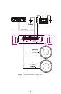
Input Mode Switch Sets the input mode of the amplifier, depending on its purpose in the
system. Can be set to Stereo Mode, Bridged Mode, or Mono Mode.
Rear Channel Input Select (4 channel only) Allows channels 3 & 4 to use either set of
inputs (front or rear) for signal.
Problem
No Audio Output
Solution
Low or no turn-on voltage. Check remote connections at amp and head unit.
Check remote voltage at amp with multi-meter, there should be around 12 volts when
head unit is on.
SETTING THE GAIN
The best way to set the gains on any amplifier is with an oscilloscope and test tone. Using
the scope will ensure the amplifier is not clipping and protect your system from being damaged
from being overdriven. If you have an oscilloscope and need help using it, feel free to call DAT
Technical Support for help.
Another way is with a multi-meter and test tone. Set the multi-meter to DC voltage, play
the test tone at 75% volume. Tune gains up until DC voltage is present, then back the gains back
down a little.
If an oscilloscope, multi-meter, or test tone is not available, find out the output signal
voltage of the head unit. Match the gain knob with that amount of voltage. It should be
between 500 mV and 5 V. If it is above 5 V, the head unit has too much signal and the amp will
clip even with the gain set at minimum. Turn system on and volume to 75%, if there is
noticeable distortion, gains should be tuned down some.
SETTING THE CROSSOVER
Select LP or HP using the Crossover Mode Switch, select desired frequency by turning the
Frequency Knob.
SETTING THE BASS BOOST
If there is a noticeable lack of low end frequency, the bass boost can be used to raise the
level of bass in the system. Turn the system on to normal listening levels and raise the bass boost
until the level of bass is satisfactory.
Caution: If "popping" , "crackling" ,or any other unusual noise is heard from the system
when using the bass boost, immediately turn the boost down to avoid damaging components
in the system. Also, if the bass sounds "muddy" or distorted, turn the bass boost down.
TROUBLESHOOTING
Blown Fuse. Check both main system fuse and amplifier fuse. If blown, replace with
fuse of same type and rating.
Speaker lead shorted. Check all speaker wire to make sure they are not shorted out
somewhere.
Blown speakers. Check speaker impedance with multi-meter, if the woofer is blown,
it will read a dead short.
Problem
Amplifier cycles on and off.
Solution
Thermal protection circuits are shutting the amplifier off. Check location of amplifier
for adequate ventilation. Check impedance at amplifier for correct load. Check
voltage at amplifier for low voltage.
Loose Connections. Check all power and signal wires to make sure they have solid
connection.
7
11
3 4