


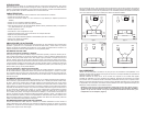
REMOVING THE GRILLE
The steel grille can be removed by loosening the four screws in the plastic clips that hold the grille,
using 3/16" Allen wrench. When the screws are removed the clips will come loose, and then the grille
will release.
WALL MOUNTING
The TFE60 and TFE60C include threaded inserts on the rear of the cabinet to work with optional wall
mount systems that allow the speakers to be mounted to a wall. We recommend Omnimount Systems
30.0 or 60.0 Series wall mounts (www.omnimountpro.com) for use with these systems.
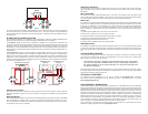
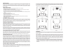
SPIKE FEET
The TFE100 and TFE200 have adjustable carpet spikes that can be used to anchor the speaker securely
to the floor on carpeted surfaces. The speakers are shipped with the spikes recessed up into the plas-
tic feet. Use the speakers in this configuration if you do not intend to use the spikes, but instead want
the speakers to rest on the feet. If you desire the speakers to rest on the spikes, follow these steps to
lower the spikes to a position below the bottom of the feet (7mm and 10mm sockets or nut drivers are
needed):
1) Carefully tip the speaker over on the rear or one of the sides.
2) With a wrench, loosen the nut on the shaft of the spike.
3) Unscrew the spike to the desired level below the bottom of the foot.
4) Tighten the nut firmly against the bottom of the speaker.
5) Repeat this process for the other three feet.
6) Carefully raise the speaker back to the upright position.
REMOVABLE FEET
The TFE60C and TFE60 have optional foam feet shipped loose in the box. If the speaker will be mounted
on a shelf or a television (not wall mounted), the feet can be applied to the bottom of the cabinet. Simply
remove the backer from the adhesives side of the feet and mount the feet near the corners of the cabi-
net.
CARE AND MAINTENANCE
Your speakers are designed to work with a wide range of electronic components. As little as 30 watts
per channel can provide enough power for most applications. If you have a large room or prefer louder
listening levels, more power may be required.
Caution: When choosing an amplifier, do not exceed the power rating of the speaker.
If you hear very high levels of audible distortion you are exceeding the capabilities of
the system. Damage can occur from this distortion, turn the volume back down until
the distortion disappears.
Use the following guidelines to maintain the appearance of your speakers. Use a soft, damp cloth to clean
the speaker cabinet. Avoid using harsh detergents or cleaning fluids. Do not vacuum any of the speaker
components, permanent damage could occur.
TECHNICAL ASSISTANCE
For additional technical assistance you can visit our website at dcmspeakers.com. Otherwise,
our technical service representatives can be reached by phone: 1-877-DCM-LOUD or by e-mail:
technical@dcmspeakers.com.
DCM WARRANTY INFORMATION
All Time Frame Evolution Series Loudspeakers purchased in the United States from an authorized DCM
dealer are guaranteed against defects in material and workmanship for a period of ten years from the date
purchased by the end user, and limited to the original retail purchaser of the product. Product found to be
defective during that period will be repaired or replaced by DCM at no charge. This warranty is void if it is
determined that unauthorized parties have attempted repairs or alterations of any nature. Warranty does
not extend to cosmetics or finish. Before presuming a defect is present in the product, be certain that all
related equipment and wiring is functioning properly. DCM disclaims any liability for other incurred dam
-
ages resulting from product defects. Any expenses incurred in the removal and reinstallation of product
is not covered by this warranty. DCM's total liability will not exceed the purchase price of the product. If a
defect is present, your authorized DCM dealer may be able to effect repairs.
Proof of purchase is required when requesting service, so please retain your sales receipt and take a
moment to register your product on line at
dcmspeakers.com.
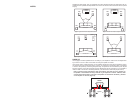
POWER AMPLIFIER
FRONT
R L
-
-
++
+
+
+
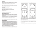
Une fois les enceintes raccordées, mettez l’électronique sous tension et faites un essai pour vérifier le
bon fonctionnement. Si le son des enceintes semble « ténu » avec peu de graves, c’est probablement
que les polarités des fils d’enceintes n’ont pas été respectées. Vérifiez à nouveau la polarité de tous les
raccordements.
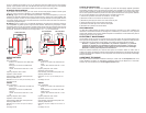
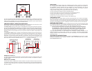
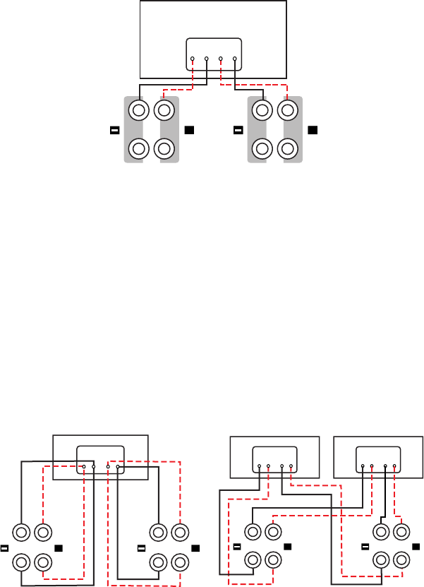
BI-CÂBLAGE ET BI-AMPLIFICATION
Si vous décidez d’effectuer un bi-câblage ou une bi-amplification, retirez les cavaliers métalliques plats
placés entre les bornes afin de ne pas endommager l’amplificateur et les enceintes.
Le bi-câblage (Figure 6) permet des améliorations notables de la transparence d’ensemble des
enceintes. Acheminez des fils de haut-parleur distincts vers les haut-parleurs basse fréquence et haute
fréquence à partir d’un même amplificateur : après avoir retiré les cavaliers, raccordez un jeu de fils de
haut-parleur aux bornes supérieures de chaque enceinte et un jeu (en général de plus gros calibre) aux
bornes inférieures. Raccordez les autres extrémités des deux jeux de fils aux sorties d’amplificateur cor
-
respondantes.
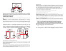
La bi-amplification (Figure 7) permet d’utiliser des amplificateurs distincts pour les sections haute et
basse fréquence de l’enceinte afin de permettre une plage dynamique plus large et une distorsion plus
faible. Après avoir retiré les cavaliers, raccordez les fils de haut-parleur des sorties d’amplificateur haute
fréquence aux bornes supérieures de chaque enceinte. Procédez de la même façon pour le raccorde
-
ment des sorties d’amplificateur basse fréquence aux bornes inférieures. Pensez à respecter les polarités
de tous les raccordements (+ au +, - au -).
FRONT
R L
- -+ +
++
R L
- -+ +
-
-
+ +
R
L
++
RETRAIT DE LA GRILLE
Pour retirer la grille d’acier, desserrez à l’aide d’une clé Allen de 3/16” les quatre vis des agrafes en
plastique maintenant la grille. Une fois les vis retirées, les agrafes sont libérées et la grille peut être
enlevée.
MONTAGE MURAL
Les modèles TFE60 et TFE60C comprennent des douilles taraudées à l’arrière de l’enceinte, compatibles
avec les systèmes à montage mural en option qui permettent le montage des enceintes sur un mur.
Nous recommandons l’utilisation des systèmes de montage mural Omnimount série 30.0 ou 60.0 (www.
omnimountpro.com) avec ces systèmes.
Figure 6
Figure 7
Amplificateur de puissance
Amplificateur basse
fréquence
Amplificateur haute
fréquence
Figure 5