


INSTALLATION CONSIDERATIONS
Hookups and Cabling: The 12 Series Equalizers are designed for nominal +4dBu levels. The equalizers can be
used with either balanced or unbalanced sources, and the outputs can be used with either balanced or unbalanced
loads, provided the proper cabling is used.
A balanced line is defined as two-conductor shielded cable with the two center conductors carrying the same signal
but of opposite polarity when referenced to ground. An unbalanced line is generally a single-conductor shielded
cable with the center conductor carrying the signal and the shield at ground potential.
Input Cable Configurations: The equalizer has an input impedance of 40k balanced and 20k unbalanced. This
makes the 12 Series Equalizers’ audio inputs suitable for use with virtually any low source impedance (under 2k ).
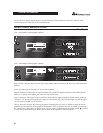
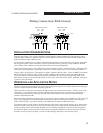
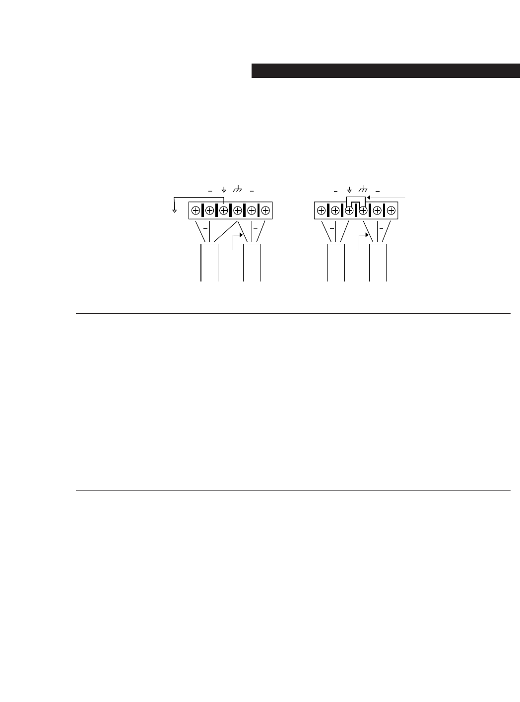
Output Cable Configurations: The equalizer’s output is capable of driving a 600 load to +18dBu. For maximum
hum rejection with a balanced source, avoid common grounding at the equalizer’s inputs and outputs. Most bal-
anced (3-conductor) cables have the shield connected at both ends. This can result in ground loops which cause
hum. If hum persists try disconnecting the shield on one or more of the cables in the system, preferably at the input
of a device, not at the output.
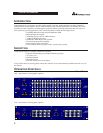
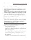
OPERATION AND APPLICATION NOTES
The dbx 12 Series Graphic Equalizers are useful audio signal processing tools in situations where precise frequency
control is required across the audible frequency spectrum.
When used with an audio spectrum analyzer the EQs can tune any acoustical environment -- from the studio to the
concert hall -- to stop ringing, increase clarity, and flatten the overall frequency response of the environment. A
real-time spectrum analyzer or other types of audio environment analyzers are very useful in determining the
amount of equalization needed.
Insert the graphic equalizer between the signal source (usually a mixer) and the power amplifiers (or the crossover if
there is one). Adjust the level and equalization as required to yield the desired system response. The long throw
faders of the EQs allow very precise settings of the equalization for accurate equalization curves.
For optimum signal-to-noise response, the gain structure of the sound system must be properly set up. Each compo-
nent of the sound system should be set at its nominal operating level, starting with the first element in the system,
usually a mixing console. Each element should be run at its nominal operating level in order to take advantage of
the maximum signal-to-noise properties of that element. Loudspeaker amplifiers, as the last element in the chain,
should be set only as loud as necessary, in order to avoid inducing unnecessary noise into the system.
++
+
++
+
++
Without Jumper in Place With Jumper in Place
jumper
optional
circuit
ground
chassis
ground
circuit
ground
chassis
ground
to system
ground
optional
Input
Cable
Output
Cable
Input
Cable
Output
Cable
Wiring Connections With Ground
OPERATION MANUAL
5
12 SERIES GRAPHIC EQUALIZERS