


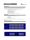


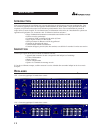

Input Gain Control: This control sets the signal level to the equalizer. It is capable of -12dB to +12dB of gain. Its
effect is apparent by viewing the OUTPUT LEVEL BAR GRAPH.
EQ Bypass: This switch removes the graphic equalizer section from the signal path. (See Block diagram on Page
8.) The BYPASS switch does not, however, affect the INPUT GAIN, or LOW CUT filters.
EQ Bypass LED: This red LED lights when the EQ is in bypass mode. Note that bypass mode only effects the
graphic equalizer section of the 12 Series EQs. The INPUT GAIN and and LOW CUT controls remain unaffected
when the EQ is bypassed.
Boost/Cut Range Selection Switch and LEDs: This switch selects which of the two boost/cut ranges the equalizer
will use, either ±6dB or ±15dB. The red LED lights when the ±15dB range is selected, and the yellow LED lights
when the ±6dB range is selected. Note that the BOOST/CUT switch is slightly recessed. This is to prevent acciden-
tal activation of the switch, possibly causing damage to other sound system components.
Output Level Bar Graph: These four LEDs indicate output level of the equalizer. The red LED is 3dB below clip-
ping and is marked as +18dBu. It monitors the level at the output of the equalizer after all other processing.
Clip LED: This LED lights whenever any internal signal level reaches 3dB below clipping which may occur when
any of the following happen: 1) the input signal is “hotter” than +22dBu, 2) excessive gain is applied by the input
gain control, or 3) excessive boost is applied using the frequency sliders.
Frequency Band Slider Controls: Each one of these slider potentiometers will boost or cut at its noted frequency
by ±6dB or ±15dB, depending upon the position of the BOOST/CUT RANGE switch. When all the sliders are in
the center detented position the output of the equalizer is flat. The frequency band centers of the 1231 are marked at
1/3rd of an octave intervals on ISO standard spacings, while the frequency band centers of the 1215 are marked at
2/3rds of an octave intervals on ISO standard spacings.
Low Cut Enable Switch: The LOW-CUT switch inserts or removes the 18dB/octave 40Hz Bessel low-cut filter
from the signal path. When the LOW-CUT switch is pushed in, the LOW-CUT filter is IN the audio path.
C
ONNECTING THE
EQ TO Y
OUR SYSTEM
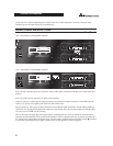
The 12 Series Equalizers have balanced inputs and outputs that can be used with any balanced or unbalanced line-
level device. For more specific information about cabling possibilities, please refer to the section entitled
Installation Considerations, Page 5.
To connect the equalizer to your sound system refer to the following steps:
• Turn off all equipment before making connections.
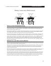
• Mount equalizer in a standard-width rack.
Install the EQs in a rack with the rack screws provided. It can be mounted above or below anything that does
not generate excessive heat. Ambient temperatures should not exceed 113° F (45°C) when equipment is in use.
Although the unit’s chassis is shielded against radio frequency and electromagnetic interference, extremely
high fields of RF and EMI should be avoided.
• Make audio connections via XLR, barrier strip, or 1/4" TRS jacks (according to application needs)
All three types of connectors for the inputs and outputs can be used for balanced or unbalanced connections.
The use of more than one connector at a time for the inputs could unbalance balanced lines, cause phase cancel-
lation, short a conductor to ground, or cause damage to other equipment connected to the equalizer. More than
one output may be used simultaneously as long as the combined parallel load is greater than 600 .
• Select the operating range with the BOOST/CUT RANGE SELECTION switch
Note: Be sure to reduce audio levels at the power amplifiers when changing the setting of this switch as it may generate an audible transient.
• Apply power to the equalizer
Connect the AC power cord to the AC power receptacle on the back of the equalizer. Route the AC power cord
to a convenient power outlet away from audio lines. The unit may be turned on and off from the rear panel
OPERATION MANUAL
3
12 SERIES GRAPHIC EQUALIZERS