


(4)
MA-09 © 2009 Dayton Audio
®
Warranty Information
Dayton Audio
®
products are constructed by industry experts, and are thoroughly tested before shipment. Dayton Audio
®
products are warranted for the period of one
year. This warranty is limited to manufacturer defects, either in materials or workmanship. Dayton Audio
®
is not responsible for any consequential on inconsequential
damage to any other unit or component or the cost for installation or extraction of any component of the audio system. In the rare case of a product failure, please
contact your place of purchase or call our Customer Support Department at (937) 743-8248.
Warranty Limitations
There are no other warranties, either express or implied, which extend the foregoing, and there are no warranties of merchantability or fitness for any particular
purpose. The warranty will not cover incidental or consequential damage due to defective or improper use of products. This includes but is not limited to burnt
voice coils, overheating, bent frames, holes in the cone, or broken lead wires.
This warranty gives you specific legal rights and you may also have other rights which vary from state to state.
Non-Warranty Service: If non-warranty service is required, the product may be sent to the Company for repair/replacement, transportation prepaid, by calling
(937) 743-8248 for details, complete instructions, and service fee charges.
NOTES ABOUT HUM:
While the MA1240 has been designed to minimize the possibility
of hum in the audio system, it is still possible that a hum will occur
in rare circumstances. Its safety grounding can create a path for
small amounts of 60 Hz energy to travel trough the line-level audio
system. While not dangerous, this energy can cause difficulty with
the auto signal sensing circuit, and at the very least will interfere
with the quiet enjoyment of your system. The first course of action
should be trying to make sure that all of the audio components are
connected to either the same electrical outlet, or at least into the
same circuit branch. Next, cable TV systems are notoriously the
culprit, so be sure to try disconnecting all coaxial feeds that are
connected to the system. If this solves the problem, install a coaxial
line isolator and reconnect the system. In the very worst case, a
line-level audio isolator/transformer connected to the line-in of the
subwoofer amplifier will usually solve the problem.
SPECIFICATIONS:
Rated Power Output: 40 Watts per channel RMS at 8 ohms
60 Watts per channel RMS at 4 ohms
Bridged Power Output: 80 Watts per channel RMS at 8 ohms
(8 ohm minimum)
Input Sensitivity: 380 mV for full output with all level
controls at max.
Input Impedance: 18K ohm
Frequency Response: 5 Hz to 72 kHz
Distortion: .09% THD 20 Hz-20 kHz @ 40W (8 ohm)
Distortion (Bridged): .30% THD 20 Hz-20 kHz @ 80W (8 ohm)
Channel Crosstalk: 80 dB
Signal to Noise Ratio: 95 dB A-weighted
Efficiency: 60%
Power Requirements: 115/230 VAC, 50 Hz/60 Hz
Stand-By Power Rating: 115V 80W; 230V 75W
Auto Turn-On Sensitivity: 18.84mV
Dimensions: 16.7” W x 4” H (including feet) x 14.25” D
Weight: 30 lbs.
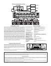
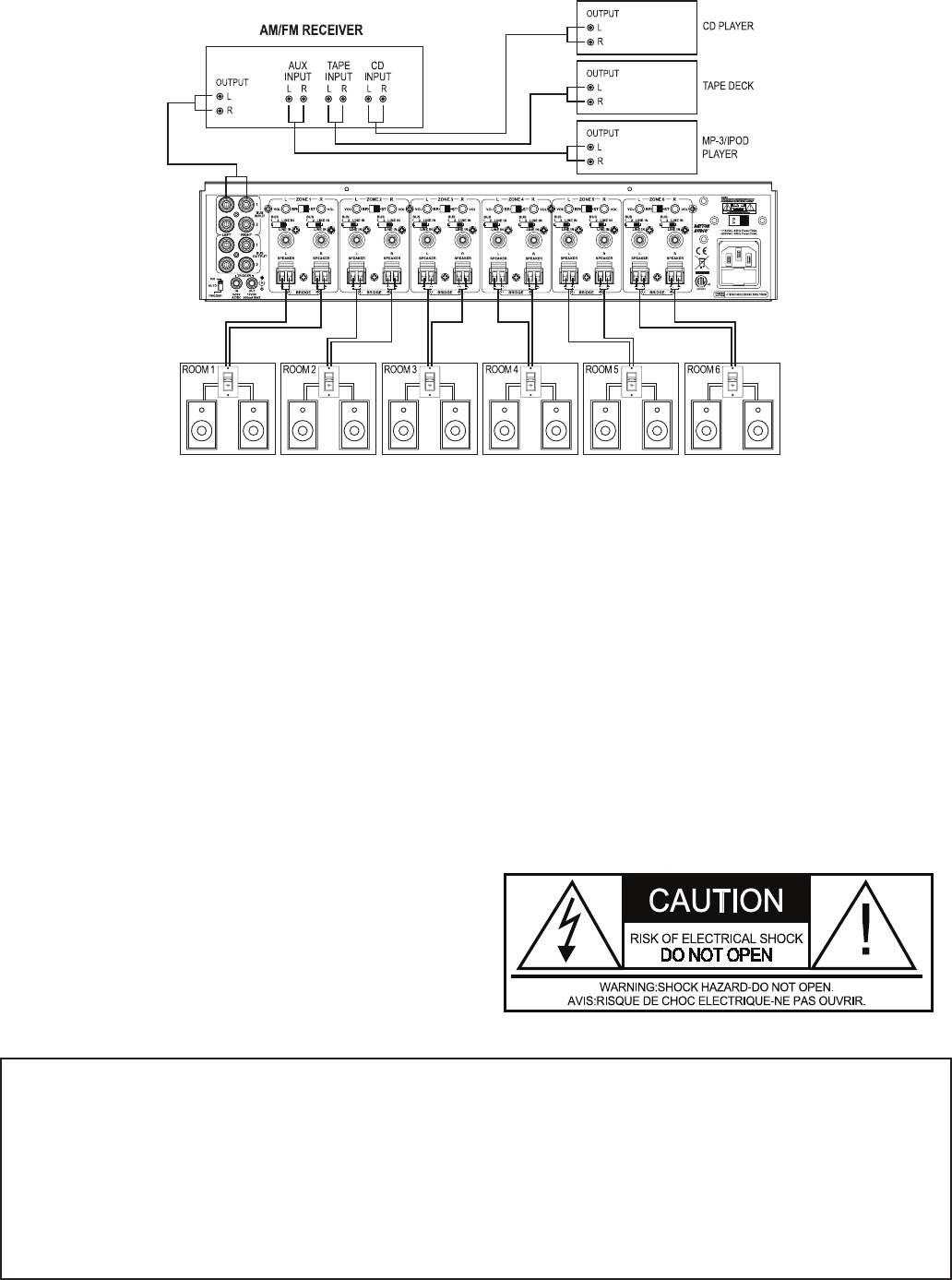
TYPICAL 6 ROOM INSTALLATION
Important Safety Instructions
To reduce the risk of electric shock, do not remove cover. No user service-
able parts inside. Refer servicing to qualified personnel. To reduce the risk
of fire and shock do not expose unit to rain or moisture. The unit should be
connected to an earth grounded AC electrical socket. The unit should be
operated in a well ventilated area. Minimum clearance is 2 inches from the
ventilation openings.
Note: Unit is set at the factory for 120V operation. Be sure to change the fuse
(4A rating) before switching to 230V operation.